RP11 - Magnetic Flux Linkage with a Search Coil
Investigate the cosine dependence of flux linkage using a stationary search coil in an alternating field, then evaluate calibration, controlled measurements and graph uncertainty.
What a search coil actually measures
A search coil detects the rate of change of flux linkage, not a steady magnetic field directly. For turns of area in a nearly uniform field,
where is between the field and the normal to the coil plane. A small coil samples the field near its centre; the uniform-field approximation becomes weaker if the field varies appreciably across its area.
In RP11, an alternating current in a large circular coil produces an alternating field. The small search coil stays at a fixed angle during each voltage reading. Set , with constant , to obtain
The oscilloscope therefore sees a sinusoidal voltage, a quarter cycle from the field. Over the chosen angle range to , the amplitude is . The measured peak-to-peak voltage is
Amplitude for a stationary search coil in an alternating field
At , the coil normal is along the field, so its plane is parallel to the large-coil plane and the amplitude is greatest. At , the field is parallel to the small-coil plane and the ideal signal is zero. A peak-to-peak voltage is non-negative: beyond , its amplitude follows , while the signed waveform reverses phase. Restricting the measurements to – avoids that ambiguity.
Connecting emf to flux change
The area under a signed emf–time pulse gives . Thus withdrawing a coil from a steady field can measure its initial linkage, provided the complete pulse is captured and the final linkage is zero. For the sinusoidal RP11 method, dividing the emf amplitude by gives linkage amplitude instead. These are two applications of Faraday's law; a stationary search coil in steady flux produces no continuous voltage.
Alignment, calibration and a controlled method
The method compares induced voltage amplitude at different angles while keeping the field amplitude, frequency and search-coil geometry unchanged. Use a large circular field coil, a small search coil, isolated low-voltage ac supply or signal generator, oscilloscope, protractor, stands and leads.
[DIAGRAM: asset_name: RP 11 - Investigate Magnetic Flux Linkage with a Search Coil - Diagram 1; asset_slug: RP 11 - Investigate Magnetic Flux Linkage with a Search Coil - Diagram 1; recommended_method: local_png; caption: The field coil connects to the ac supply and the centred search coil to one oscilloscope input and common. The inset defines the angle from the search-coil normal to the field.; description: The field coil connects to the ac supply and the centred search coil to one oscilloscope input and common. The inset defines the angle from the search-coil normal to the field.]
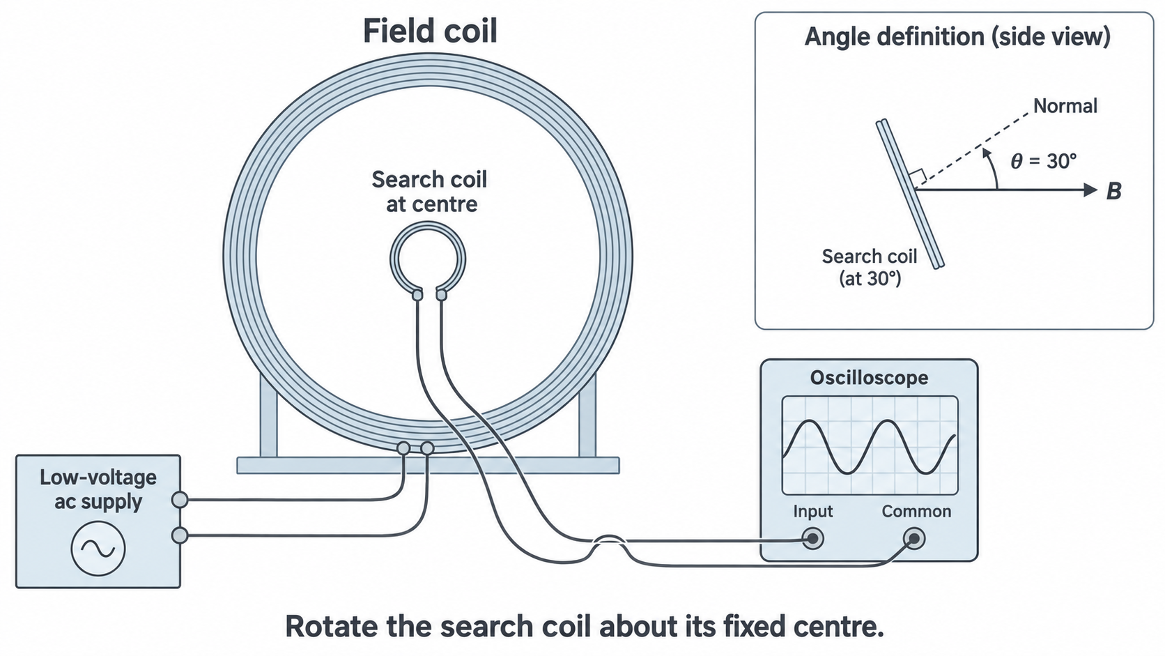
- Support the field coil securely and connect it to the low-voltage ac source. Keep within its current rating; use an ac ammeter if needed. Excess current can heat the coil, alter its resistance and damage insulation.
- Mount the search coil at the field-coil centre. Put the rotation axis through its centre so changing angle does not move it into a different field. Align the planes for , and read the protractor perpendicular to its scale to reduce parallax.
- Connect the two search-coil terminals across one oscilloscope channel, input and common. Keep the leads close together or twisted so their loop area does not pick up a substantial extra induced signal.
- Establish the zero reference and check voltage/time calibration using the instrument's known calibration output or another suitable known signal. Record probe attenuation, volts per division and time per division. A high input resistance makes the measured terminal voltage a good approximation to the coil's emf.
- Choose a stable sinusoidal frequency, a stationary triggered trace and enough voltage sensitivity to make the signal large without clipping. Record the frequency and field-coil current amplitude. A higher frequency can improve the signal, but choose it before taking the angle series; coil impedance can alter current if frequency changes at fixed source voltage.
- At each angle from to , for example every , hold the coil still and measure crest-to-trough divisions. Convert to , repeat the reading and record a mean. Revisit occasionally to check drift, and repeat the series in reverse order.
Keep , field-coil current amplitude, the search coil's and , and its centre fixed. Changing oscilloscope sensitivity is allowed if every reading is converted using its actual setting. Record raw divisions, settings, angle, repeats, mean and uncertainty with units in the table. Switch off before rewiring, secure the stands and check for coil or load-resistor heating. Written planning prepares for the experiment; successful practical performance still requires observation in the laboratory.
Testing the cosine law and finding field strength
If the controls are constant, should be proportional to . Calculate cosine in degree mode and plot mean voltage against cosine, with clear units. A straight-line trend is necessary, but an intercept consistent with zero within uncertainty is also needed to support direct proportionality.
Continue this lesson.
You’re previewing NovaLearn without an account. Create a free account to read the rest.
Create free account