3.7.4.2 - Parallel Plate Capacitor
Relate capacitance to plate geometry and dielectric material, explain molecular polarisation, and distinguish a capacitor connected to a battery from one isolated after charging.
Plate geometry and electric field
A parallel-plate capacitor has two flat conducting plates with overlapping area , separated by an insulating gap of width . One plate carries and the other . Here is the overlapping area of one plate, not the sum of both plate areas.
[DIAGRAM: asset_name: 7.4.2 - Parallel Plate Capacitor - Diagram 1; asset_slug: 7.4.2 - Parallel Plate Capacitor - Diagram 1; caption: Parallel conducting plates of overlapping area A and separation d. The field points from the positive plate to the negative plate, the cell polarity matches the plate charges.; description: Parallel conducting plates of overlapping area A and separation d. The field points from the positive plate to the negative plate, the cell polarity matches the plate charges.]
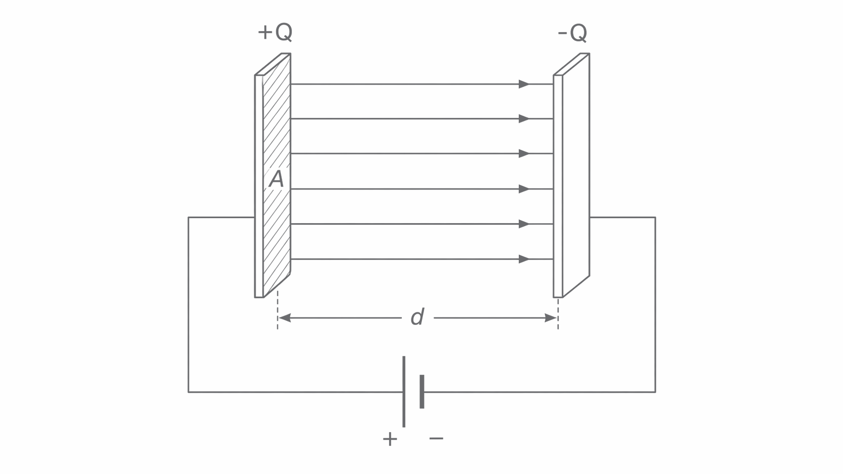
When the separation is small compared with the plate dimensions, the field away from the edges is approximately uniform. Then . Fringing at the edges makes the ideal model less accurate for widely separated or poorly aligned plates. Plate charge flows through the connecting wires; an intact dielectric does not conduct electrons from plate to plate.
How area, spacing and material set capacitance
Increasing the overlapping plate area allows more charge at a given pd; reducing the separation also increases capacitance. For parallel plates completely filled by a uniform dielectric,
Parallel-plate capacitance
The permittivity of free space is . Relative permittivity is dimensionless; it is 1 in vacuum and approximately 1 in air. The equation assumes negligible edge effects and no air gaps in the dielectric.
For vacuum, the uniform-field relation , together with , gives . The factor describes the increase produced by the dielectric. Thus doubling doubles , whereas doubling halves it. Doubling a square plate's side length quadruples its area. Thin dielectric layers and large folded or rolled electrode areas allow large capacitance in a small volume.
For square plates of side , separation and , use and . This gives
Relative permittivity and its measurement
Relative permittivity, also called the dielectric constant in this context, is the ratio of a material's permittivity to that of free space. For the same plate geometry,
Here is the fully dielectric-filled capacitance and is the vacuum capacitance (approximated by air). A dielectric constant of 7.0 means seven times the capacitance for the same geometry. It also means seven times the plate charge at the same pd, since . The charge ratio is invalid if the pd changes.
To determine , measure capacitance using a capacitance meter with air between two plates, then insert a sheet filling the same gap. Keep overlapping area and separation fixed; measure sheet thickness or use spacers, because inserting a thicker sheet would change two variables. Subtract a measured lead/stray capacitance if significant, then calculate . For corrected readings and , . Air pockets lower the measured increase.
The same apparatus can investigate at fixed , or at fixed . Measure several spacings; plot against , keeping leads in the same position and plates parallel. A straight line through the origin after stray-capacitance correction supports the model. Its gradient is ; a nonzero intercept can indicate uncorrected stray capacitance.
Continue this lesson.
You’re previewing NovaLearn without an account. Create a free account to read the rest.
Create free account