RP06 - EMF and Internal Resistance
Measure a cell’s terminal pd at different currents to determine emf and internal resistance. Use a controlled discharge, a consistent graph and an uncertainty estimate to test whether one pair of cell parameters describes the results.
The model tested by the practical
The emf is energy supplied per unit charge; the internal resistance represents the cell’s internal pd drop when supplying current. For a discharging cell, energy conservation gives , so
If both parameters remain approximately constant over the investigation, terminal pd plotted vertically against current is a straight line with intercept and gradient .
The intercept corresponds to zero cell current, when the internal drop is zero. The negative gradient means an increase in current produces a larger internal pd and a smaller terminal pd. Internal resistance itself is positive; a negative graph gradient does not mean negative resistance.
The model is an approximation over a chosen range and timescale. Temperature, state of charge and time after connecting a load can change a real cell’s behaviour. A straight trend and repeat checks support the approximation; the word “fresh” alone does not establish it. This practical determines the cell’s values under the recorded conditions, not a universal value for every battery of its type.
Connecting the meters and collecting paired readings
Connect the cell, switch, ammeter and adjustable load in one series loop. Connect a high-resistance voltmeter directly across the cell terminals, spanning the ideal emf and internal resistance together in the equivalent circuit.
[DIAGRAM: asset_name: RP 06 - Investigation of the EMF and Internal Resistance of Electric Cells - Diagram 1; asset_slug: RP 06 - Investigation of the EMF and Internal Resistance of Electric Cells - Diagram 1; caption: The voltmeter spans the complete real-cell model. Ammeter, switch, protective resistor and rheostat are in the external series loop. Close the switch briefly for each reading.; description: The voltmeter spans the complete real-cell model. Ammeter, switch, protective resistor and rheostat are in the external series loop. Close the switch briefly for each reading.]
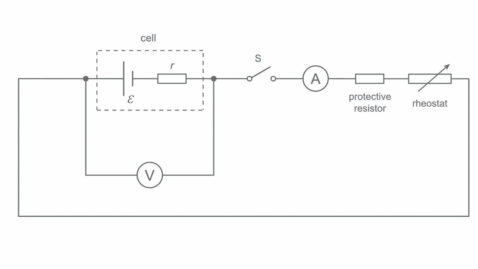
Select a cell and resistor ratings suitable for a school investigation. Start at high load resistance and use a protective series resistor if needed to limit the largest current. Check meter polarity, ranges and wiring with the switch open. Never put the ammeter alone across the cell or deliberately short the cell to obtain a graph intercept. Avoid high-current rechargeable sources unless the equipment and supervision are specifically suitable. Components can become hot: disconnect and allow cooling before handling.
With the external switch open, record the voltmeter reading as an approximate emf check. Close the switch briefly and record and as one pair after a consistent short settling time; then open it. Adjust the load and repeat for several settings across a safe useful current range. Record repeats at each setting and retain the raw pairs; a table should state , , instrument resolution/range and measurement timing.
Fixed load resistors can replace a rheostat. Their exact resistance is not needed if both and are measured, but their values and power ratings determine the accessible safe current range. Choose settings from pilot readings instead of aiming for a prescribed current regardless of the cell.
Controlling cell state and choosing the current range
The plotted independent variable is current, changed by adjusting the external load. The dependent variable is terminal pd. Keep the same cell, measurement connections and approximately the same temperature and state of charge throughout the set.
Open the switch between readings to reduce discharge and heating. Take pairs at a consistent delay after switching, because chemical polarisation and heating can make pd drift. Use a reasonably fresh, stable cell, but still repeat an early load setting near the end. If its reading has shifted beyond uncertainty, investigate drift rather than averaging the whole set as though it had one constant emf and resistance. The sign of a temperature effect on internal resistance depends on the cell; do not assume heating always increases it.
A wide safe current range makes the terminal-pd change easier to distinguish from voltage uncertainty and constrains the gradient. Include low-current values to reduce extrapolation to zero current. A very small internal resistance may produce a pd change too small for the available meters; forcing a larger current is not always a suitable solution.
Repeat paired readings to assess scatter. Tight, clean connections and appropriate meter ranges improve stability. A changing resistance elsewhere in the external load changes the measured operating point but does not, by itself, violate if the two readings are simultaneous and taken at the correct terminals.
Continue this lesson.
You’re previewing NovaLearn without an account. Create a free account to read the rest.
Create free account