3.13.5.2 - Sequential Logic
Follow stored binary and decoded states through clock edges, resets and wrap-around, then choose counter blocks for frequency division, decimal displays and timed sequences.
Stored state and counter inputs
A counter stores a state: its outputs show how many active clock edges have occurred since a known starting condition. This makes it sequential logic. The same present clock level can accompany different counts because the earlier sequence matters.
For the example counter in this lesson, CK triggers on a rising edge, U/D = 1 selects up-counting, and MR = 1 resets the count immediately to zero. These are specified device behaviours, not universal meanings of the voltage levels on all counters.
| Input | Function in this example |
|---|---|
| CK | Each 0-to-1 transition advances one count. Falling edges do not. |
| U/D | Selects up or down at the next active edge. Changing it alone does not add a count. |
| MR | Active-high asynchronous reset: while high, the count is held at zero regardless of CK. |
Asynchronous reset acts without waiting for a clock edge. A task using a synchronous reset or a falling-edge clock must state that different behaviour. Likewise, a bar or bubble marks an active-low input; it does not by itself establish which direction an up/down control selects.
[DIAGRAM: asset_name: E.5.2 - Sequential Logic - Diagram 1; asset_slug: E.5.2 - Sequential Logic - Diagram 1; caption: Four binary output bits have place values 1, 2, 4 and 8; description: Four binary output bits have place values 1, 2, 4 and 8]
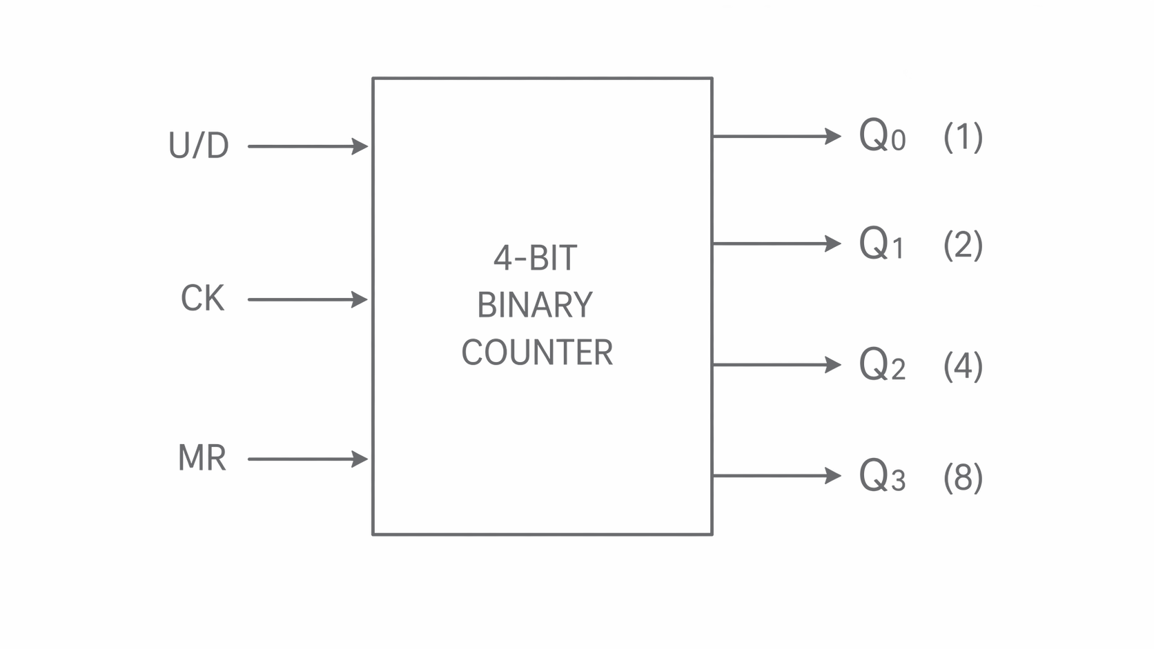
The output is the least significant bit (value 1). Read a four-bit number as , with values 8, 4, 2, 1. Thus 1010 represents , not ten independent output lines.
An N-bit binary counter has states, from 0 to . A four-bit up-counter wraps from 1111 to 0000 on the next active edge; a down-counter wraps from 0000 to 1111. This natural wrap-around is not an external reset command. Outputs labelled through are six bits: 64 states, largest value 63.
Clock edges and frequency division
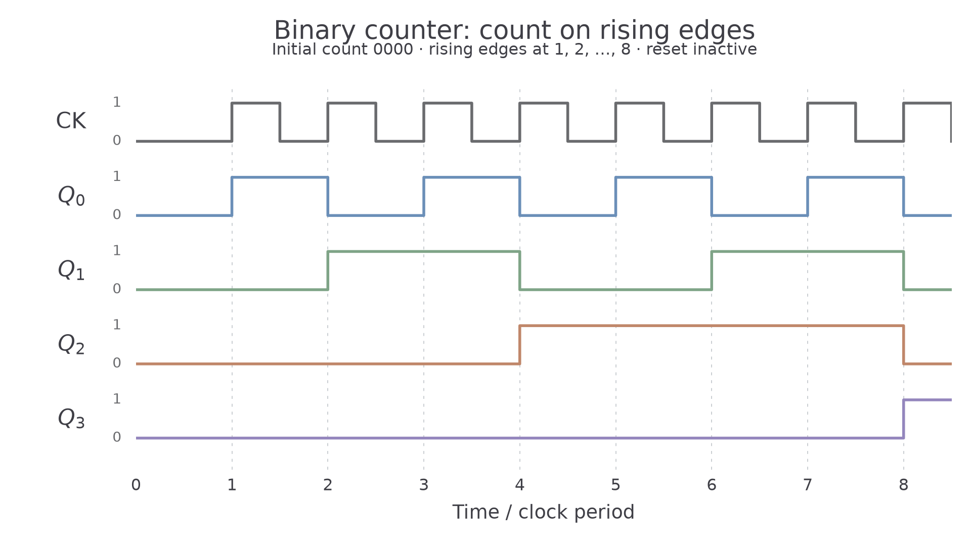
A timing diagram must state the initial count and the active clock edge. Read the count between transitions, after any propagation delay. Do not count both sides of each pulse.
The diagram starts at 0000, has no reset during the shown interval, and counts up at each rising edge. Vertical guides mark those edges. Immediately after edge 3 the bits read 0011; after edge 4 they read 0100. The lower bit returns to zero as the next bit takes the carry.
[DIAGRAM: asset_name: E.5.2 - Sequential Logic - Diagram 2; asset_slug: E.5.2 - Sequential Logic - Diagram 2; caption: Binary outputs change only at the numbered rising clock edges; description: Binary outputs change only at the numbered rising clock edges]
Why each bit divides the frequency
toggles at every edge, but needs two edges to complete a low–high–low cycle. Its frequency is therefore half the clock rate. needs four clock periods per cycle, eight, and sixteen.
Here n is the output index starting at zero. This relation is for a freely running binary counter with fixed direction, without resets or inhibited counts. It must not be applied unchanged to a truncated modulo counter.
For a clock, has frequency , so its period is . Eight clock periods separate a rise from the following fall; sixteen separate successive rises. That distinction prevents the common factor-of-two error.
To obtain 1 Hz from an ideal 32768 Hz clock requires division by , hence output . A real oscillator's accuracy limits the resulting timebase: division preserves its fractional frequency error.
Reset logic for modulo-n counting
A modulo-n counter repeats after n states. To obtain stable counts 0 through n − 1 from an up-counting binary block, logic can detect the next count n and activate its reset input.
For the example below, MR is active-high and asynchronous, the counter starts at zero and counts upward, and propagation delays are neglected except for the brief reset transient. These conditions matter: a circuit designed this way is not automatically a modulo-n down-counter.
Detect the first unwanted count
For modulo 11, the first unwanted value is . Connect , and to AND, then feed its output to MR. The first count reached from zero with all three bits high is 11. The output 1011 exists briefly while the reset acts; the stable sequence is 0, 1, …, 10, 0.
[DIAGRAM: asset_name: E.5.2 - Sequential Logic - Diagram 3; asset_slug: E.5.2 - Sequential Logic - Diagram 3; caption: AND of Q3, Q1 and Q0 resets the up-counter at 1011; description: AND of Q3, Q1 and Q0 resets the up-counter at 1011]
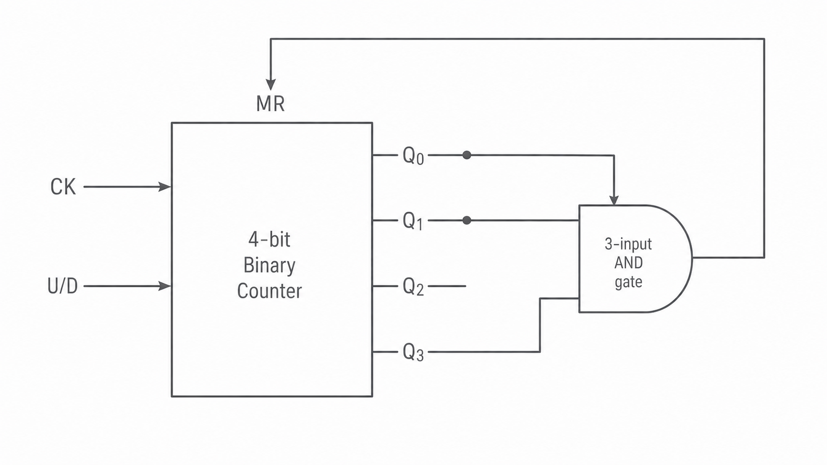
This detector also becomes high at 1111. That does not matter in the stated up-counting sequence, which resets before reaching it. It would matter if the count could be preset or driven through a different sequence. If only the exact code 1011 must be recognised, include as well: .
Choose enough bits to represent the reset value n when n is not a power of two. For example, three bits can detect 6 and give six stable states. When , the N-bit counter already wraps naturally after n states; no extra reset detector is needed to represent the unrepresentable value .
An active-low reset would need an appropriately inverted detector, such as NAND of the selected high bits. Match the reset polarity to the question's block. A manual active-high reset M and an automatic detector D can both request a reset through OR: .
Continue this lesson.
You’re previewing NovaLearn without an account. Create a free account to read the rest.
Create free account