RP10 - Force on a Current-Carrying Wire
Required practical 10 investigates how the force on a wire depends on magnetic flux density, current and active wire length using a top-pan balance. The wire and magnets must be supported independently, so the balance reveals the magnetic reaction force. A useful investigation controls geometry, records signed changes and tests a relationship against uncertainty.
What the balance actually measures
A straight active length carrying current perpendicular to a uniform field experiences force magnitude . In this arrangement the wire is clamped to a stand and the magnet assembly rests on the balance. The balance measures the force on the magnets, not the force directly on the wire.
For an upward force on the wire, the wire exerts an equal downward force on the magnets. The balance reading increases. Reverse the current without changing the field: the force on the wire is now downward and the reading decreases. This is Newton's third law, not an increase or decrease in the magnets' actual mass.
Let be the current-off reading and the current-on reading. Define the signed change ; then the magnitude of magnetic force is
Convert grams to kilograms first. An increase of corresponds to downward on the magnets and upward on the wire. Taring with current off is a convenient way of setting the initial displayed value to zero.
Equal positive and negative currents provide another check. If their readings are and , the magnetic mass-change magnitude is , provided the current magnitudes and geometry match and the offset is stable. Taking half the difference cancels a common balance offset; it does not cure drifting zeros, changing current or mechanical contact.
Setting up and recording a current sweep
Use a low-voltage DC supply, switch, ammeter, current-limiting variable resistor and stiff test wire in one series circuit. Keep the wire on independent clamps and the magnet/yoke assembly centred on a stable balance. The active wire section passes across the gap perpendicular to the north-to-south field and must not touch the magnets, yoke or balance.
[DIAGRAM: asset_name: RP 10 - Investigate How the Force on a Wire Varies with Flux Density, Current and Length - Diagram 1; asset_slug: RP 10 - Investigate How the Force on a Wire Varies with Flux Density, Current and Length - Diagram 1; caption: End-on force geometry and a separate series circuit for controlling current; description: Current out of the page crosses a rightward magnetic field. Wire force is up, magnet reaction down. The circuit arrows show conventional current when the switch is closed.]
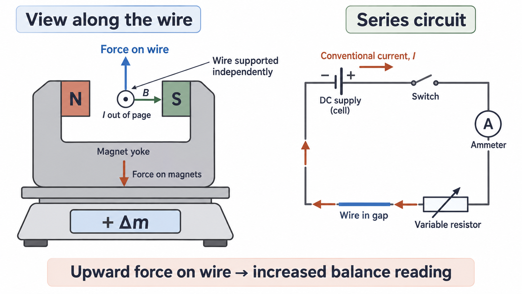
Read the ammeter's polarity and range before connecting it: current enters its positive terminal. Use a range suitable for the expected current and the instrument's rating. The diagram's circuit is a connectivity view; it is separate from the end-on spatial view. Close the switch only after the connections have been checked.
- With current off, check that the wire clears both pole faces. Record or tare the balance zero.
- Start at low current and choose a safe range that produces changes well above balance fluctuations. Use the actual measured current, not a supply dial setting.
- At each setting record the current and settled balance reading together. Take several settings across the range, then repeat the sweep and record all repeats.
- Switch off between readings when needed and allow the wire to cool. Recheck the current-off reading to detect zero drift. Repeat a suspicious point after checking the apparatus rather than silently deleting it.
- Measure the active wire length with a ruler at eye level. Interpolate between scale marks, account for both endpoint readings and record the unit. For a straight wire spanning the pole region, pole width approximates active length only when edge effects are small.
High current heats the wire and resistor; select a rated resistor and limit current and contact time. Switch off before moving wires or magnets, allow cooling before handling, and keep fingers clear when bringing strong magnets together. Secure the clamps so nothing can fall onto the balance.
Record a table with current in amperes, each signed balance change in grams, the mean change and the converted force. A digital display's last digit is resolution, not a guarantee of accuracy. Keep the original readings so someone else can check the averaging and conversions.
Controlling the field, length and orientation
To investigate current, change only while holding , and the right-angle orientation fixed. Use the same magnet arrangement, pole separation and wire position. A wire moved towards the edge may sample a weaker, less uniform field even if the magnets themselves are unchanged.
Heating increases the wire's resistance. With a fixed supply voltage, this can reduce current, so record current at the same time as force and allow cooling between runs. Measuring the actual current handles one consequence of heating, but does not justify unlimited heating or movement of the wire. Check for upward/downward sweep differences that might indicate drift.
Keep connecting leads off the balance and place return sections of the circuit outside the strong field. Forces on additional wire sections can alter what the apparatus measures. The wire must stay perpendicular to the field throughout; a tilt decreases the relevant perpendicular component.
A valid conclusion needs enough distinct settings to reveal a trend, repeats to assess scatter, and a force signal large enough relative to uncertainty. Repetition can reveal random variability and anomalous readings. It does not remove a miscalibrated balance, an incorrect active length or consistently tilted geometry.
Using a force-current gradient to find the field
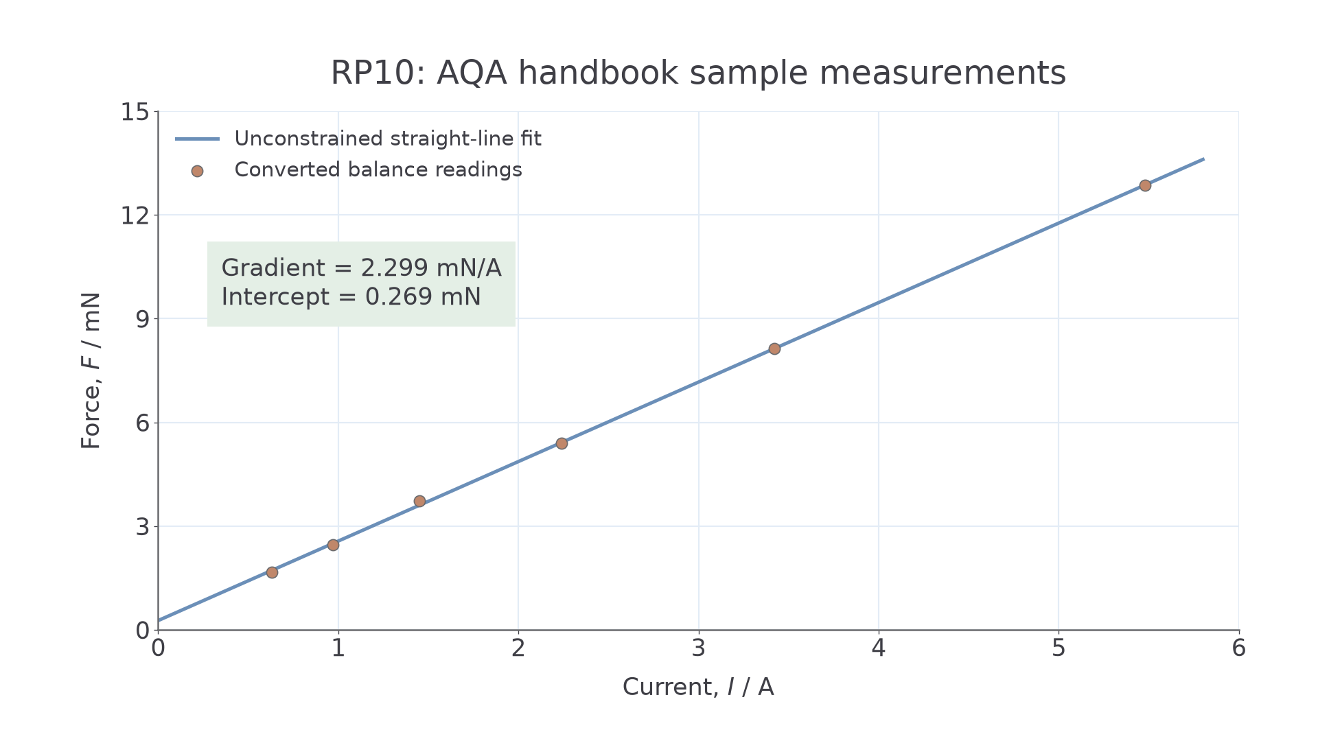
With field and active length fixed, . A graph of force in newtons on the vertical axis against current in amperes on the horizontal axis has gradient in , so . Use a large triangle on the best-fit line rather than two adjacent measured points.
The following sample readings are from the AQA practical handbook, with . Here the listed positive changes correspond to the orientation that increases the balance reading.
| 0.63 | 0.17 | 1.67 |
| 0.97 | 0.25 | 2.45 |
| 1.45 | 0.38 | 3.73 |
| 2.24 | 0.55 | 5.40 |
| 3.42 | 0.83 | 8.14 |
| 5.48 | 1.31 | 12.85 |
[DIAGRAM: asset_name: RP 10 - Investigate How the Force on a Wire Varies with Flux Density, Current and Length - Diagram 2; asset_slug: RP 10 - Investigate How the Force on a Wire Varies with Flux Density, Current and Length - Diagram 2; caption: Handbook force-current data with an unconstrained straight-line fit; description: Exact force conversion of the table and a least-squares straight line. Force axis is in millinewtons. The fit has a small positive intercept.]
Continue this lesson.
You’re previewing NovaLearn without an account. Create a free account to read the rest.
Create free account