3.11.2.4 - Engine Cycles
Connect the four physical strokes to ideal and measured pressure–volume cycles, then distinguish fuel input, cylinder work and useful shaft output.
The four strokes of a petrol engine
A stroke is one movement of a piston between its extreme positions. A four-stroke petrol engine completes one working cycle in two crankshaft revolutions; there is one power stroke per cycle per cylinder.
- Induction: the piston moves down; the inlet is open and a fuel–air mixture enters. In a naturally aspirated engine its pressure is slightly below atmospheric pressure.
- Compression: the valves are closed and the piston moves up. Work done on the mixture raises its pressure and temperature. A spark ignites it near the end of compression.
- Power (expansion): combustion produces high-pressure gas that pushes the piston down. Both valves are closed for most of this stroke; the exhaust opens near its end.
- Exhaust: the piston moves up while the exhaust valve is open, pushing burnt gas out. The inlet then opens for the next cycle.
[DIAGRAM: asset_name: C.2.4 - Engine Cycles - Diagram 1; asset_slug: C.2.4 - Engine Cycles - Diagram 1; caption: The four strokes alternate piston direction. The compressed mixture is ignited near minimum cylinder volume.; description: The four strokes alternate piston direction. The compressed mixture is ignited near minimum cylinder volume.]
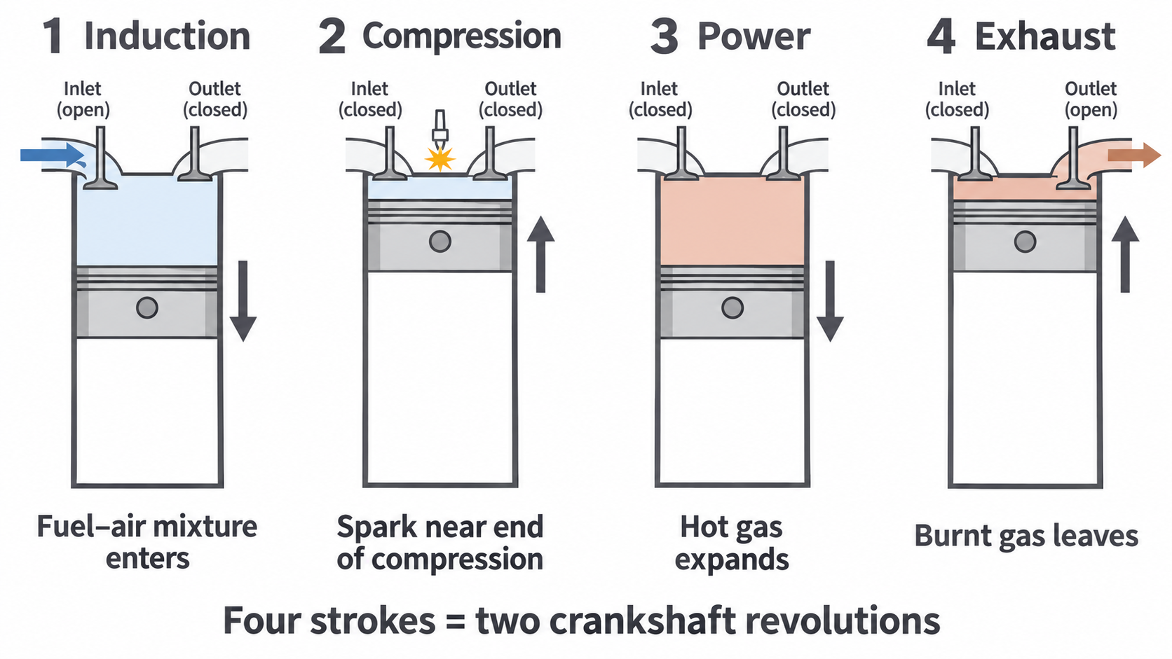
Expansion takes place at higher pressure than compression over much of the same volume range, so the gas supplies net work. The actual cylinder exchanges matter during induction and exhaust; it is not a closed fixed-mass system throughout all four strokes. The ideal Otto cycle below models its main energy transfers with a fixed gas amount.
Diesel compression ignition
A diesel engine draws in air only during induction. A large compression raises the air temperature; near the end of compression, fuel is injected and ignites in the hot air without a spark. Expansion and exhaust then follow the same broad piston sequence as in a petrol engine.
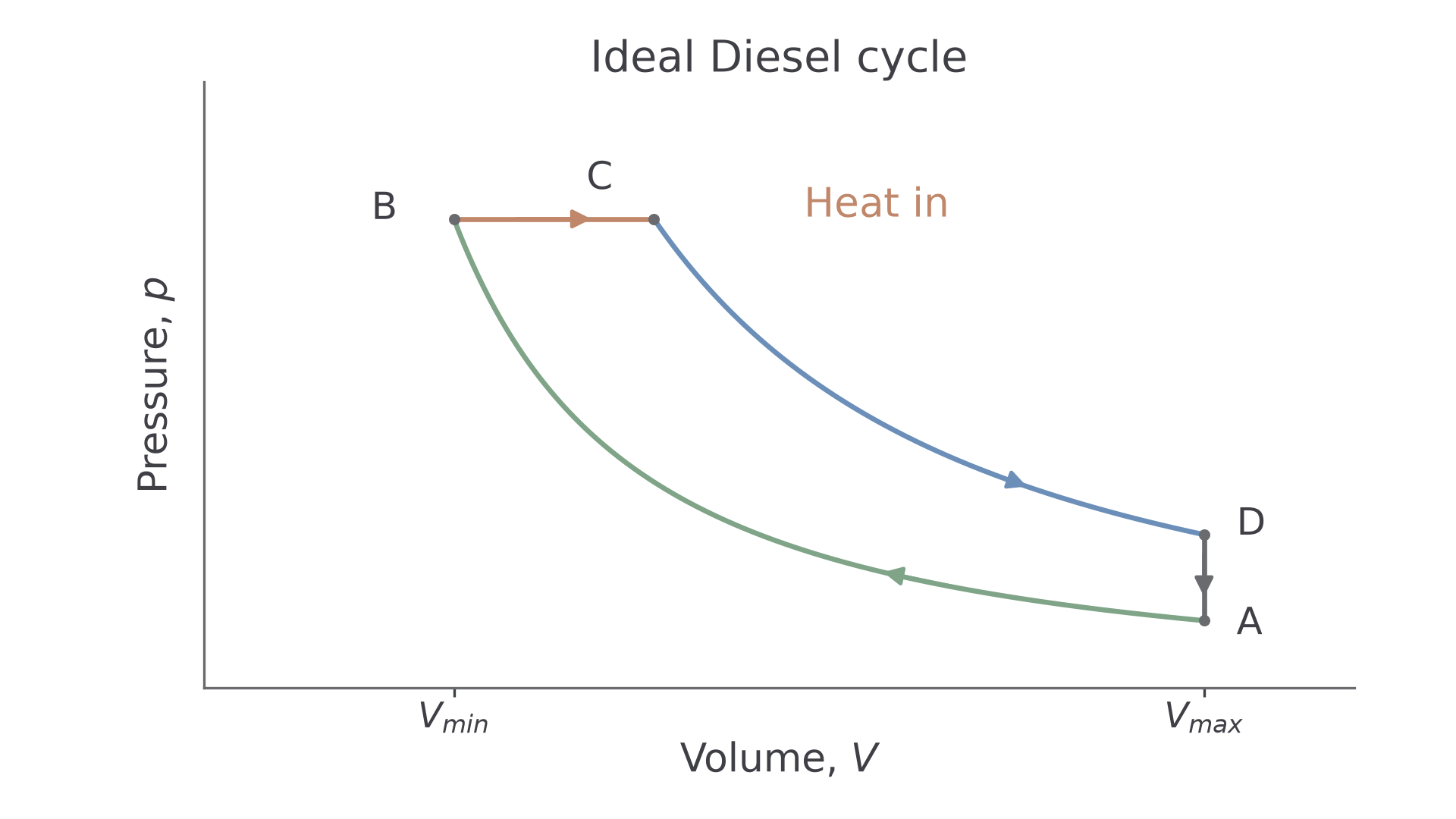
The idealised heat-addition step differs. Rapid petrol combustion is modelled as heat supplied at constant volume. Progressive diesel combustion as the piston starts down is modelled as heat supplied at constant pressure. These are modelling approximations: neither real pressure nor volume remains perfectly fixed during combustion.
Higher compression ratios can be used in a diesel because the charge being compressed is air, without a premixed fuel charge that could ignite prematurely. Detailed valve construction, injector design and engine hardware are outside the required scope.
Ideal cycles and measured indicator diagrams
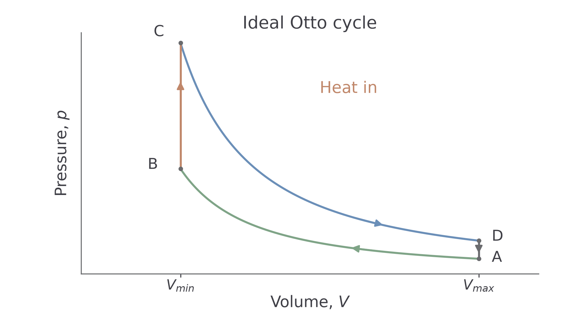
An indicator diagram plots cylinder pressure against volume over a cycle. An air-standard theoretical model uses the same fixed amount of ideal gas, reversible adiabatic compression/expansion, and ideal heat addition/rejection. Combustion is represented by supplied heat and exhaust replacement by rejected heat; this does not mean the real engine has an external burner.
Otto model for petrol
Starting at , large volume and low pressure: is adiabatic compression; is constant-volume heat input; is adiabatic expansion; is constant-volume heat rejection.
[DIAGRAM: asset_name: C.2.4 - Engine Cycles - Diagram 2; asset_slug: C.2.4 - Engine Cycles - Diagram 2; caption: The ideal Otto loop has vertical heat-addition and heat-rejection legs and two adiabatic curves.; description: The ideal Otto loop has vertical heat-addition and heat-rejection legs and two adiabatic curves.]
Diesel model
is adiabatic compression; is constant-pressure heat input; is adiabatic expansion; is constant-volume heat rejection. Both cycles run clockwise.
[DIAGRAM: asset_name: C.2.4 - Engine Cycles - Diagram 3; asset_slug: C.2.4 - Engine Cycles - Diagram 3; caption: The ideal Diesel loop replaces the Otto vertical heat-input step with a horizontal expansion at constant pressure.; description: The ideal Diesel loop replaces the Otto vertical heat-input step with a horizontal expansion at constant pressure.]
Departures in a real engine
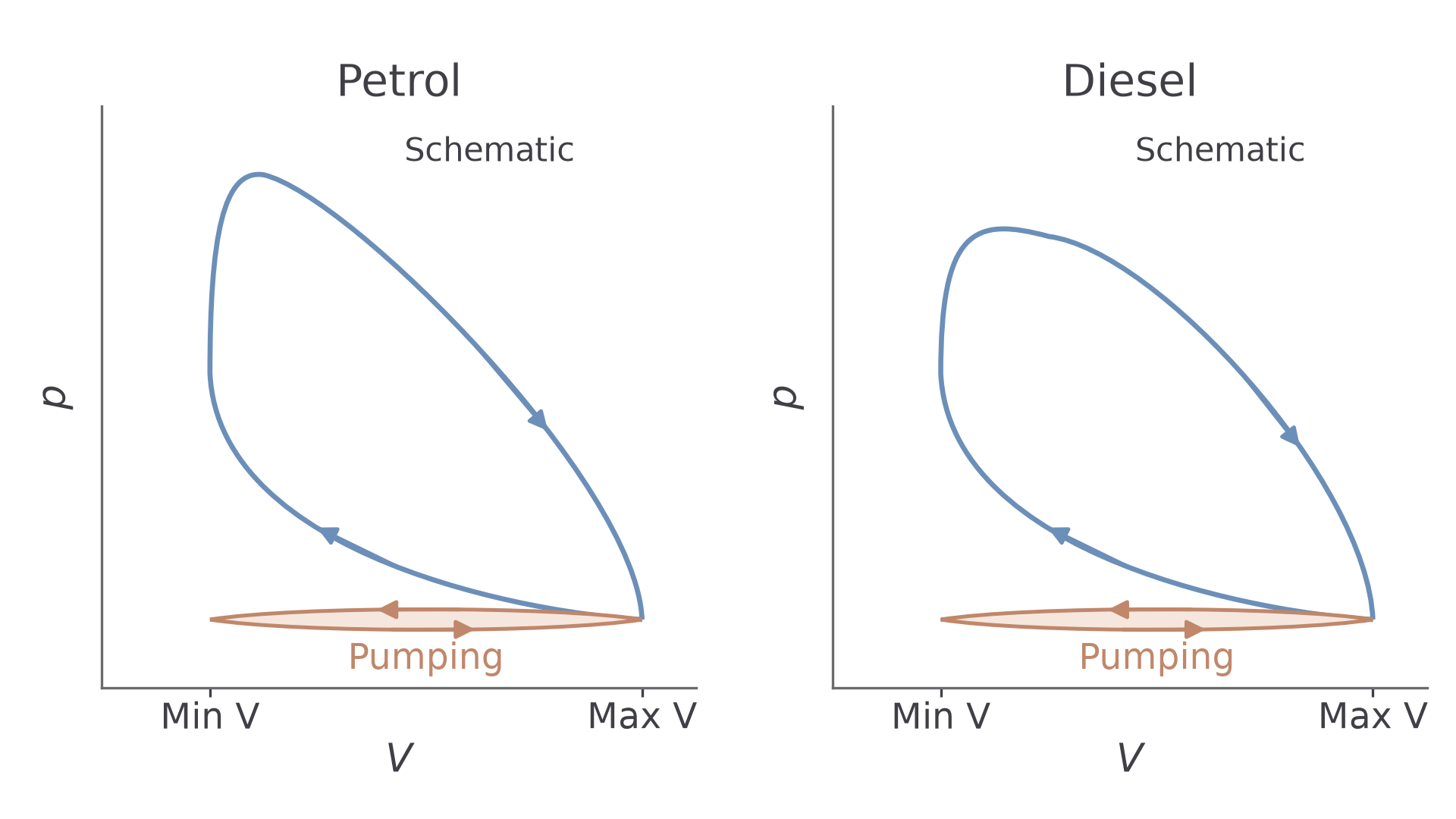
Pressure sensors and piston/crank-position information produce a measured indicator diagram. Combustion takes time, so pressure rises while the piston moves and corners are rounded. Heat transfer to walls reduces pressure during expansion. Incomplete combustion can reduce energy transferred from a given fuel input. Early exhaust opening reduces the late expansion area. For a naturally aspirated engine, induction below atmospheric pressure and exhaust above it form a small anticlockwise pumping loop, subtracting work.
[DIAGRAM: asset_name: C.2.4 - Engine Cycles - Diagram 4; asset_slug: C.2.4 - Engine Cycles - Diagram 4; caption: Illustrative petrol and diesel traces show rounded transitions and a negative pumping loop. These are schematics, not measured data.; description: Illustrative petrol and diesel traces show rounded transitions and a negative pumping loop. These are schematics, not measured data.]
Continue this lesson.
You’re previewing NovaLearn without an account. Create a free account to read the rest.
Create free account