3.13.1.1 - MOSFET
An insulated gate lets a small sensor signal control a larger load current. Learn to interpret N-channel enhancement-mode MOSFET characteristics and calculate what happens in a switching circuit.
An insulated gate controls the channel
An N-channel enhancement-mode MOSFET controls a drain–source current using the voltage on an insulated gate. The gate is a control input, not the route through which the load current enters.
The source (S) and drain (D) contact two N-type regions in a P-type substrate. The gate (G) is separated from the semiconductor by a thin oxide insulator. With no gate–source voltage there is no conducting N-channel linking source and drain. A sufficiently positive gate attracts electrons to the region just beneath the oxide, creating that channel.
[DIAGRAM: asset_name: E.1.1 - MOSFET - Diagram 1; asset_slug: E.1.1 - MOSFET - Diagram 1; caption: Insulated gate above an induced N-channel; description: Simplified conducting MOSFET: source and drain contact the N-type regions; oxide insulates only the gate from the induced channel.]
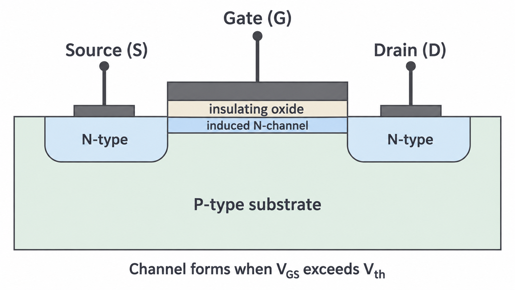
The picture shows the channel after it has formed. It is not a permanent wire. The gate's electric field changes the conductivity of the channel without a steady current passing through the oxide. This gives the MOSFET a very high input resistance. A small transient current charges or discharges the gate when its voltage changes, but the steady gate current is negligible.
For the usual circuit with drain more positive than source, conventional current flows from drain to source; electrons move from source to drain. These opposite directions refer to the same charge flow.
Voltages are measured relative to the source
The source is the reference terminal for both voltages used to describe MOSFET operation. It need not be at earth potential.
Here is gate–source p.d., is drain–source p.d., and is drain–source current. For example, if the gate, source and drain are at , and , then and . Comparing the gate's directly with a threshold would give the wrong comparison.
The threshold voltage, , is the gate–source voltage at which appreciable channel conduction begins. Below it the enhancement device is approximately off; above it the channel conducts increasingly well. Threshold is the onset of conduction, not a guarantee that the device is already a good low-resistance switch. The gate drive must be high enough for the required load current, as shown by the characteristics or device data.
is the small drain–source leakage current measured with gate and source joined, so , at a specified . It is not the current entering the gate and not the normal on-state load current. In an ideal switch calculation this leakage is neglected. Raising within the normal operating range does not replace the positive gate drive needed to form the channel.
Reading transfer and output characteristics
A characteristic specifies which variable is changed and which is held fixed. Mixing these up can make a correct-looking graph interpretation describe the wrong experiment.
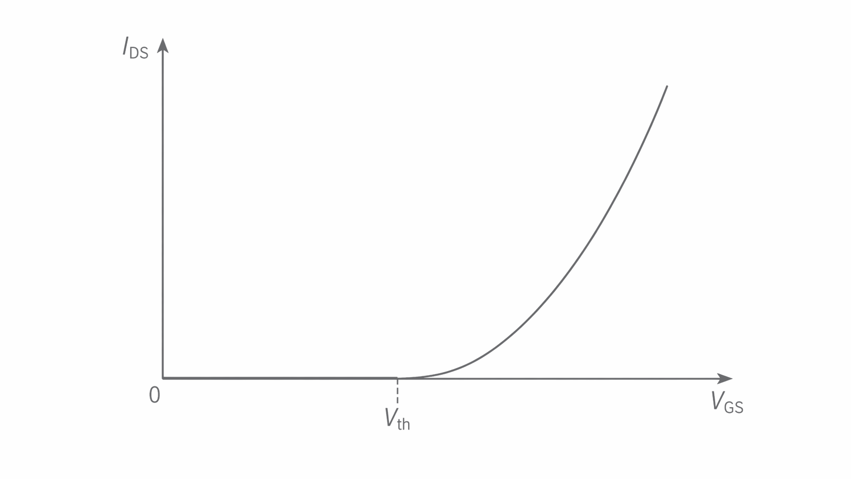
The transfer characteristic plots against at fixed . It shows negligible current below threshold, then a rising current above threshold. A real threshold is specified at a small test current; it is not an infinitely sharp physical step.
[DIAGRAM: asset_name: E.1.1 - MOSFET - Diagram 2; asset_slug: E.1.1 - MOSFET - Diagram 2; caption: Transfer characteristic at fixed drain–source voltage; description: Schematic transfer characteristic at fixed drain–source p.d.: appreciable current begins near the gate–source threshold; axes are qualitative.]
Continue this lesson.
You’re previewing NovaLearn without an account. Create a free account to read the rest.
Create free account