3.3.2.3 - Refraction at a Plane Surface
When light crosses a boundary between two transparent substances, its speed changes. That change of speed changes the direction of travel unless the ray arrives along the normal. In this lesson you will connect ray diagrams to refractive index, Snell's law, total internal reflection, and the way optical fibres carry information.
Refractive index
The refractive index of a substance tells you how much light slows down in that substance compared with a vacuum. A larger refractive index means light travels more slowly and the substance is more optically dense.
Refractive Index
The refractive index of a substance is the ratio of the speed of light in a vacuum to the speed of light in that substance.
Refractive Index
Here, is the speed of light in a vacuum and is the speed of light in the substance. For the transparent materials in this lesson, and light travels more slowly than in a vacuum. The refractive index of air is very close to 1, so for A-level work you should recall that the refractive index of air is approximately 1.
When light enters a substance and slows down, its frequency stays constant. The source fixes the oscillation frequency, and the boundary must be driven at that same frequency. Hence wavelength decreases with speed: . Refractive index is a dimensionless ratio, not a speed or a measure of mass density.
Snell's law
Refraction happens because one side of a wavefront reaches the new substance before the other side. If the new substance has a lower light speed, that first part slows down while the rest of the wavefront is still moving faster. The wavefront pivots, and the ray changes direction.
In the figure below, notice that both angles are measured from the normal and that the ray bends towards the normal when it enters the more optically dense substance.
[DIAGRAM: asset_name: 3.2.3 - Refraction at a Plane Surface - Diagram 1; asset_slug: 3.2.3 - Refraction at a Plane Surface - Diagram 1; recommended_method: retained_png; caption: Refraction angles are measured from the normal; description: A plane boundary between substance 1 and substance 2. A normal is drawn at the boundary. An incident ray in substance 1 makes angle theta_1 to the normal and a refracted ray in substance 2 makes angle theta_2. The refracted ray bends towards the normal when substance 2 is more optically dense.]
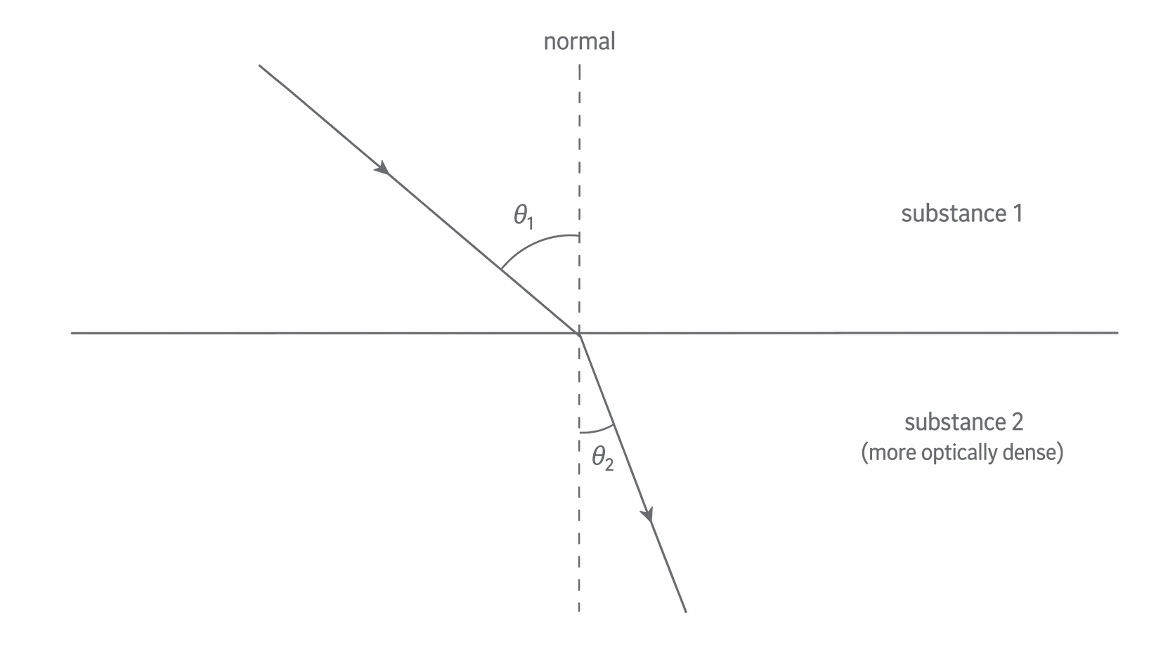
Light bends towards the normal when it enters a more optically dense substance and away from the normal when it enters a less optically dense substance. If it travels along the normal, there is no change in direction.
Using the wavefront geometry for a boundary between two substances gives the relationship
.
Replacing the speeds with refractive indices gives Snell's law.
Snell's Law
Here, and are the refractive indices of the two substances, and and are the angles to the normal. If the first substance is air, you can often take .
During refraction, the speed and wavelength change, but the frequency stays constant. Always measure the angles from the normal.
Total internal reflection
When light travels from a more optically dense substance into a less optically dense one, it bends away from the normal. As the angle of incidence increases, the angle of refraction also increases. Eventually the refracted ray reaches and runs along the boundary.
Critical Angle
The critical angle is the angle of incidence in the more optically dense substance for which the angle of refraction in the less optically dense substance is .
The figure below compares the three key cases at a glass-air boundary, so focus on how the refracted ray moves from leaving the glass to skimming the surface and then disappearing when total internal reflection begins.
[DIAGRAM: asset_name: 3.2.3 - Refraction at a Plane Surface - Diagram 2; asset_slug: 3.2.3 - Refraction at a Plane Surface - Diagram 2; caption: Increasing the incident angle from glass to air reaches the critical angle, then total internal reflection; description: True-angle geometry for glass of index 1.50 to air of index 1.00. Incidence 30.0 degrees gives refraction 48.6 degrees. At incidence 41.8 degrees the refracted ray follows the boundary. At 55.0 degrees total internal reflection has equal incident and reflected angles.]
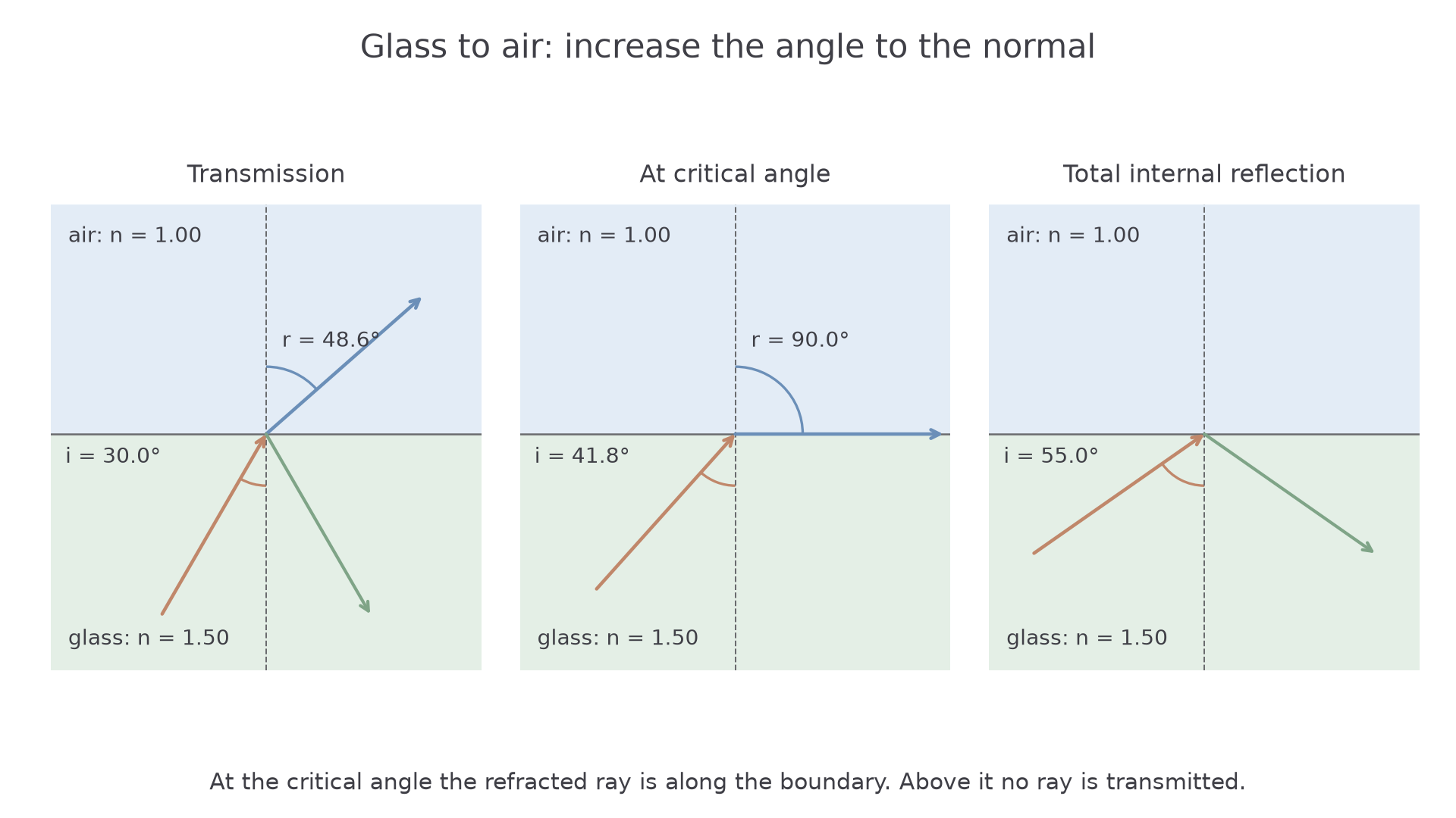
Applying Snell's law at the critical angle gives
.
Since , the critical-angle equation is:
Critical Angle
Total internal reflection happens only when two conditions are both true:
- light is travelling from the more optically dense substance to the less optically dense substance
- the angle of incidence is greater than the critical angle
For example, at a glass-air boundary with and ,
, so .
Step-index optical fibres
Optical fibres use total internal reflection to guide light along a thin flexible core, even when the fibre bends gently.
Optical fibres are used in telecommunications to carry pulses of light over long distances, and in medical endoscopes to deliver light into the body and return an image.
A step-index optical fibre has a core with a higher refractive index surrounded by cladding with a slightly lower refractive index. For this specification, you only need the step-index case, where the refractive index changes sharply at the core-cladding boundary.
In the figure below, notice that the core has the higher refractive index and that the light stays trapped by repeated total internal reflection at the core-cladding boundary.
[DIAGRAM: asset_name: 3.2.3 - Refraction at a Plane Surface - Diagram 3; asset_slug: 3.2.3 - Refraction at a Plane Surface - Diagram 3; caption: A continuous ray reflects within the higher-index fibre core; description: Equal-angle zigzag ray confined to a straight core of index 1.50 surrounded by cladding of index 1.45. A ray at 10 degrees to the fibre axis meets each wall at 80 degrees to its normal, above the 75.2 degree critical angle.]
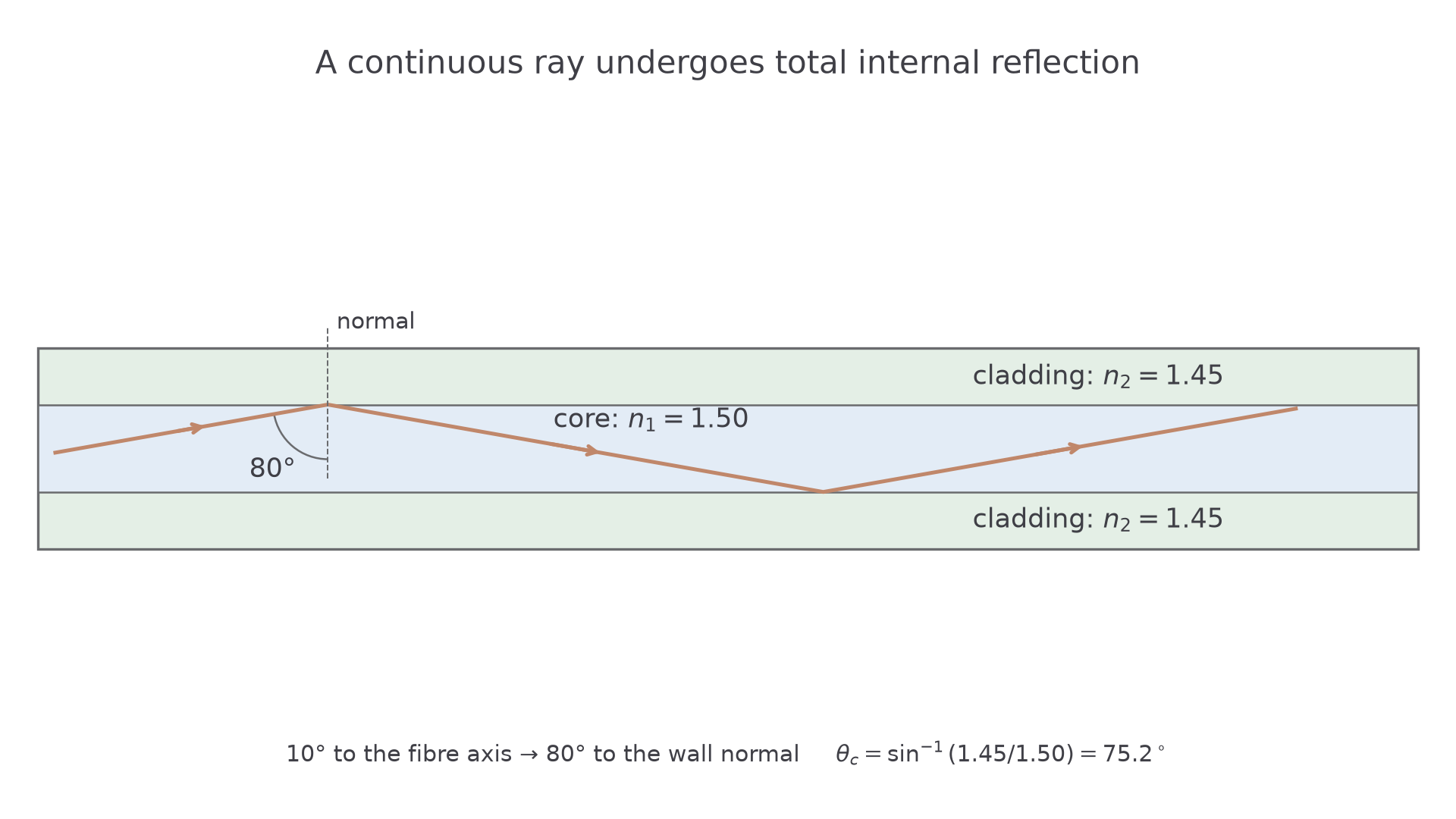
The cladding matters for three main reasons:
- it provides the lower refractive index needed for total internal reflection at the core-cladding boundary
- it reduces light leakage and crossover between neighbouring fibres
- it protects the core from surface damage that would let light escape
For the drawn fibre, . A ray making to the fibre axis strikes the wall at to its normal, so it undergoes total internal reflection. The two angles are complementary. Bending the fibre too sharply can reduce the incidence angle below the critical angle and cause leakage; a higher-index core alone does not trap every incident ray.
Absorption and dispersion
Real fibres do not transmit signals perfectly. Over long distances, two broad problems matter: the signal can get weaker, and the pulses can spread out.
Absorption reduces the amplitude of a pulse because some of the light energy is absorbed by the glass. If the pulse becomes too weak, the receiver may not be able to distinguish it from noise. Low-loss glass reduces absorption. Repeaters restore the weakened signal after transmission; they do not prevent absorption in the glass.
Pulse Broadening
Pulse broadening is the spreading out of a pulse as it travels along an optical fibre. If neighbouring pulses overlap, information can be lost.
Two important causes of pulse broadening are:
- modal dispersion: different rays take different paths through the core, so they take different times to reach the end; this is reduced by using a sufficiently narrow core that supports fewer propagation modes
- material dispersion: different wavelengths travel at slightly different speeds in the glass, so parts of the same pulse separate; this is reduced by using monochromatic light, usually from a laser
These effects matter because a communication system relies on clear, separate pulses. If pulses merge, the receiver cannot distinguish successive bits. For example, pulses initially wide and separated by between centres can become distinguishable less reliably when broadened beyond . Reducing the pulse rate gives more separation but reduces the information rate. Raising the source brightness can help against attenuation; it does not undo pulse overlap.
Remember these key results: , air has refractive index about 1, , and for light travelling from the denser to the less dense substance. In fibres, cladding enables total internal reflection, absorption reduces amplitude, and dispersion causes pulse broadening.