3.7.5.3 - Magnetic Flux and Flux Linkage
Flux describes a magnetic field passing through an area. Flux linkage also counts how many turns of a coil share that flux. Both change when a coil rotates, even if the field strength stays constant.
Magnetic flux through an area
For a uniform field perpendicular to a flat surface, magnetic flux is
Here is magnetic flux density in tesla and is the surface area in . Flux is measured in webers, , with . Increasing either the field strength or the area increases the flux. The field-line picture helps visualise this, but flux is not literally a count of physical lines.
[DIAGRAM: asset_name: 7.5.3 - Magnetic Flux and Flux Linkage - Diagram 1; asset_slug: 7.5.3 - Magnetic Flux and Flux Linkage - Diagram 1; caption: Maximum flux through an area when the magnetic field is normal to it; description: A flat area in a uniform field whose direction is perpendicular to the plane, giving flux BA.]
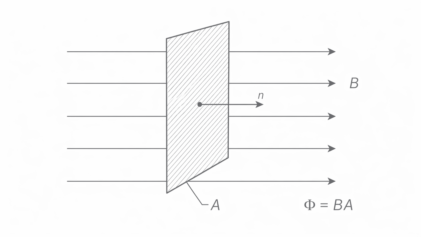
"Field normal to the area" means perpendicular to its plane, not parallel to the surface. For a rectangular loop, use its enclosed area: a by loop encloses . Convert both lengths before multiplying; .
Flux linkage and the area of one turn
A coil with turns has flux linkage when each turn is linked by the same flux . For identical turns normal to a uniform field,
The area is the area enclosed by one turn. It is neither the wire's metal cross-section nor the sum of all turn areas followed by another multiplication by . Turns are a dimensionless count, so linkage has SI unit ; "weber turns" also makes the distinction explicit.
Doubling doubles linkage but does not double the flux through each turn. Similarly, rewinding the same wire into more, smaller turns need not increase linkage: both and the area per turn must be considered. If turns link different fluxes, their individual fluxes must be added instead of assuming one common .
For example, each of 200 turns enclosing in a normal field has . The linkage is .
Measuring the angle from the normal
A surface's normal is a line perpendicular to its plane. Let be the angle between the magnetic field and a chosen normal. Only the field component along that normal contributes to flux:
[DIAGRAM: asset_name: 7.5.3 - Magnetic Flux and Flux Linkage - Diagram 2; asset_slug: 7.5.3 - Magnetic Flux and Flux Linkage - Diagram 2; caption: The angle for flux is between the magnetic field and the coil normal; description: Edge-on vertical coil with horizontal normal. B is inclined to the normal and B cos theta lies along the normal. Vector lengths are schematic.]
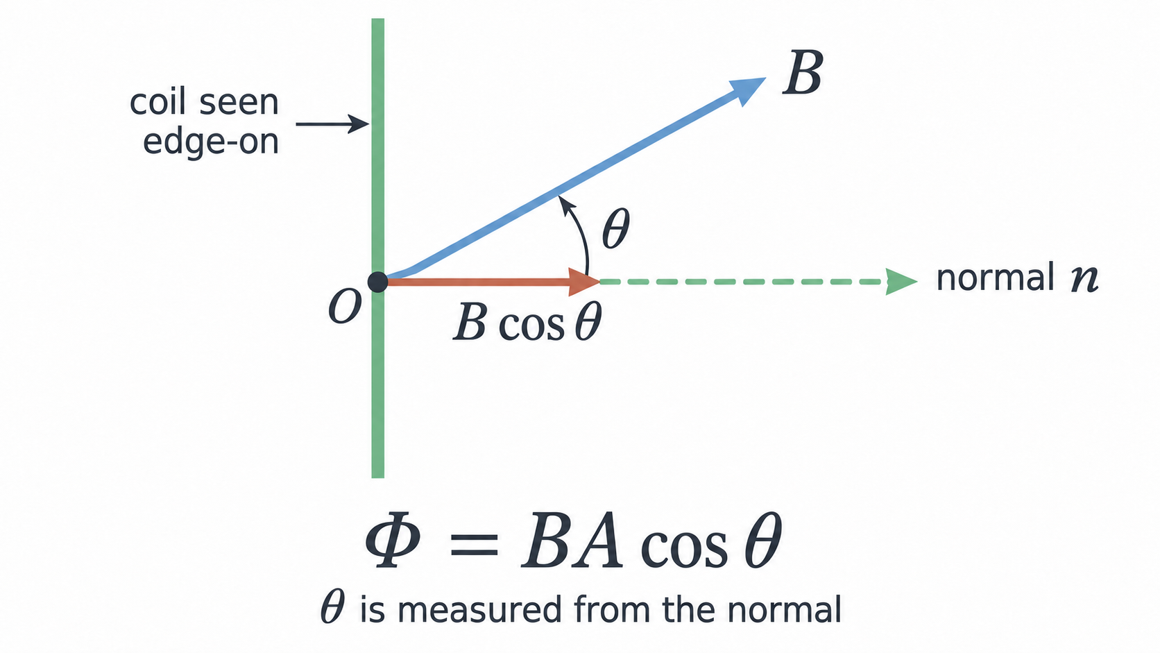
At , the field is perpendicular to the coil plane and linkage is maximum, . At , the field lies in the plane and linkage is zero. At , linkage is : the field passes through in the opposite sense relative to the chosen normal. The sign is directional, not a negative field strength.
If the angle is given to the plane, convert using . Then . A coil plane to the field therefore has half its maximum linkage, not times the maximum.
Continue this lesson.
You’re previewing NovaLearn without an account. Create a free account to read the rest.
Create free account