3.13.4.1 - Inverting Amplifiers
Negative feedback lets an op-amp produce a predictable inverted output. Follow the current through the input and feedback resistors to derive the gain, then check when the required output is physically possible.
Negative Feedback and Virtual Earth
An inverting amplifier feeds the signal through to the op-amp's input. The resistor returns the output to that same junction, and the input is connected to ground, our reference.
[DIAGRAM: asset_name: E.4.1 - Inverting Amplifier Configuration - Diagram 1; asset_slug: E.4.1 - Inverting Amplifier Configuration - Diagram 1; caption: Inverting amplifier with feedback to the summing junction and the non-inverting input grounded; description: Inverting amplifier with feedback to the summing junction and the non-inverting input grounded.]
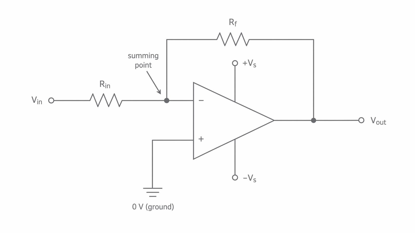
The feedback is negative because it corrects a change. Suppose the junction becomes slightly positive while the input stays at zero. The op-amp drives its output negative, drawing current through and pulling the junction back towards zero. The energy delivered at the output comes from the power supplies, not from the small input signal.
For an unsaturated op-amp, . A very large open-loop gain needs only a very small input difference to produce a finite output. Thus negative feedback holds .
Virtual earth
A point held at approximately by the circuit's action, without a direct connection to ground.
Equal potentials do not mean a wire connects the two inputs. The high input resistance means negligible current enters either op-amp input. Current can still pass through the junction from one external resistor to another. Virtual earth requires negative feedback and linear operation; it is not an unconditional property of the terminal.
Deriving the Signed Gain
The virtual-earth potential and negligible op-amp input current provide two different pieces of information. The first sets the voltage across each resistor; the second lets us equate their currents.
For positive , define towards the junction and from the junction towards the output. Kirchhoff's current law gives , because no current is lost into the op-amp. Ohm's law then gives
Equating and rearranging,
The minus sign follows from the potential difference across the feedback resistor, not from an arbitrary rule about op-amps. A negative input reverses both defined currents; the same signed equation still works. AQA requires this derivation, including the physical assumptions, rather than just the final formula.
For example, and give . With , the same current needs , so .
Continue this lesson.
You’re previewing NovaLearn without an account. Create a free account to read the rest.
Create free account