3.13.1.2 - Zener diode
A reverse-biased Zener can provide a known voltage if its current is kept within the right range. Use its characteristic and simple resistor calculations to distinguish a working reference from an unsafe or unreliable circuit.
Anode, cathode and reverse breakdown
A Zener diode is manufactured for controlled operation in reverse breakdown. Its useful reference voltage comes from reverse bias, not from ordinary forward conduction.
The bent bar in the symbol marks the cathode; the other terminal is the anode. Forward bias puts the anode at a higher potential than the cathode. Reverse bias puts the cathode at a higher potential than the anode.
[DIAGRAM: asset_name: E.1.2 - Zener Diode - Diagram 1; asset_slug: E.1.2 - Zener Diode - Diagram 1; caption: Zener symbol with anode and cathode; description: Zener symbol: anode at left and cathode identified by the bent bar at right.]
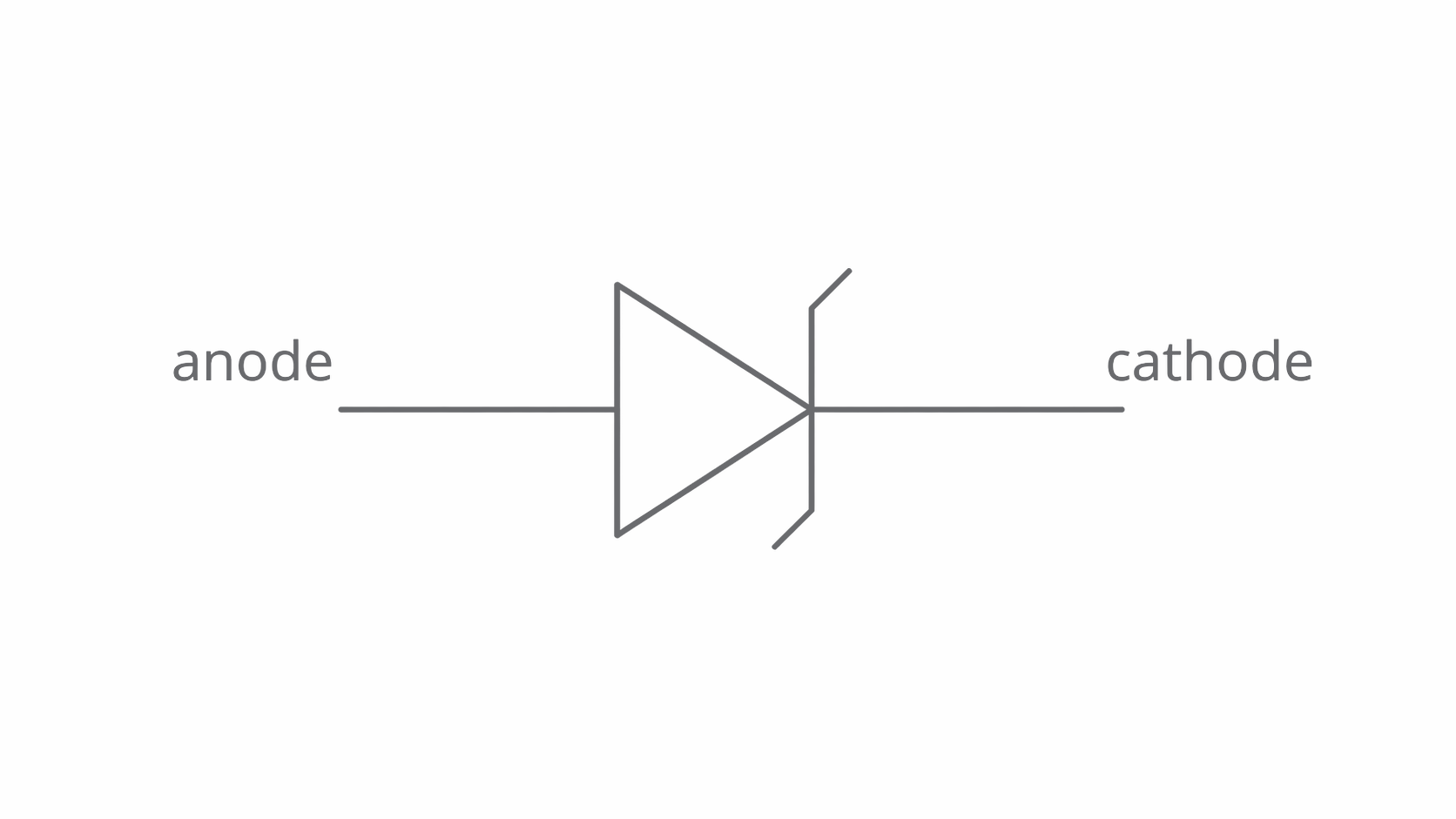
In forward bias it behaves much like an ordinary silicon diode: the current rises rapidly at a p.d. of roughly , depending on current and temperature. In reverse bias the current is initially very small. At the Zener breakdown voltage, , the reverse current becomes large while the voltage changes relatively little.
A Zener is not immune to damage. Breakdown operation is safe only within its current and power ratings. A suitable external resistor limits the current; an ordinary diode is not normally intended to be operated in reverse breakdown.
The nearly vertical breakdown characteristic
The current–voltage graph uses positive voltage and current for the forward direction, from anode to cathode. Reverse operation therefore lies at negative voltage and negative current; and reverse-current magnitudes are normally quoted as positive numbers.
[DIAGRAM: asset_name: E.1.2 - Zener Diode - Diagram 2; asset_slug: E.1.2 - Zener Diode - Diagram 2; caption: Reverse breakdown and the Zener operating-current range; description: Schematic signed Zener I–V curve, not to scale: forward conduction near 0.7 V and reverse breakdown near −VZ. Dashed reverse-current levels show operating limits.]
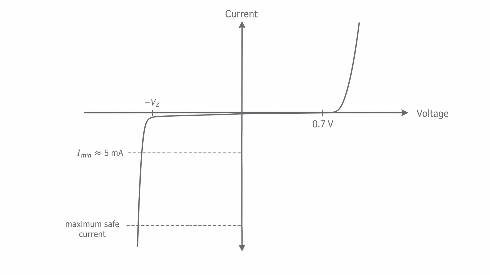
The steep reverse branch means a large change in current produces only a small change in p.d. It is steep, not exactly vertical, so the output is approximately constant. The minimum operating current, , is the reverse current needed to work in this steep region. A typical teaching value is about , but an actual problem or device specification may give a different value.
Below , the diode is near the bend or below breakdown and a reliable reference cannot be assumed. Above the maximum safe current, may overheat it. Thus both a minimum and a maximum matter:
For example, if the reverse current rises from to while the p.d. rises only from to , the large current change accompanies just a voltage change. This is the graph feature that makes a reference possible.
A current-limited reference voltage
A reference circuit connects the reverse-biased Zener in series with a resistor across a supply. The output is taken across the diode, with a measuring or comparator input that draws negligible current.
Continue this lesson.
You’re previewing NovaLearn without an account. Create a free account to read the rest.
Create free account