3.10.5.4 - CT Scanner
A projection X-ray superimposes structures along each beam path. Computed tomography combines transmission measurements from many angles to reconstruct a cross-sectional map of attenuation, separating structures that overlap in a single view.
From projections to cross-sectional images
A conventional radiograph records the accumulated attenuation along each source-to-detector path. A dense region near the source can produce the same transmitted intensity as an equivalent region near the detector. A single projection therefore does not uniquely reveal where along the path the attenuation occurred.
Computed tomography (CT) records paths through the same slice from many directions. A structure that overlaps another in one projection generally lies along different measured paths in another. A computer combines these constraints to reconstruct the distribution of attenuation within the slice. A slice is a two-dimensional cross-section representing a finite thickness of tissue, not a complete three-dimensional image by itself. Adjacent reconstructed slices can be combined into a three-dimensional representation.
CT separates overlapping structures and distinguishes small differences in attenuation. This is different from simply magnifying a radiograph. Magnification makes the existing projection larger; it does not add the missing directional measurements.
Tube, beam, detectors and computer
A CT scanner collects transmission data using a moving X-ray tube, a restricted beam, an array of detectors and a computer. Keep their roles separate: detectors measure signals; the computer reconstructs the image.
The tube rotates around the patient so X-rays cross the same region from many angles. In a common arrangement the detector array rotates opposite the tube. At each angle, different detector elements record radiation transmitted along neighbouring paths through the slice. The beam passes through the patient to the detectors; CT does not work by reflecting X-rays back to the tube.
[DIAGRAM: asset_name: B.5.4 - CT Scanner - Diagram 2; asset_slug: B.5.4 - CT Scanner - Diagram 2; caption: Two successive CT viewing angles illustrate transmission measurements used for reconstruction; description: Two successive CT viewing angles illustrate transmission measurements used for reconstruction.]
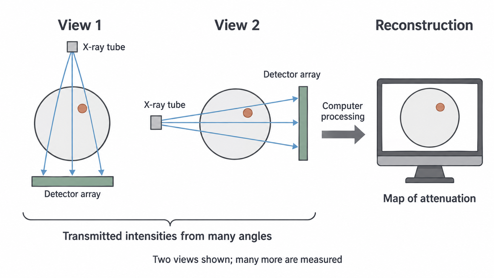
Only a few rays and two positions are shown. The patient and internal structure remain fixed; the source and detector change position. A real reconstruction uses many more paths and angles than this illustration.
Narrow beam and monochromatic model
Collimation restricts the beam thickness along the patient so the measurement refers to a thin section. The beam can fan out across that section to reach an array of detectors. “Narrow” therefore does not require it to be a single pencil ray.
The AQA model specifies a monochromatic beam: all photons have one energy. Since attenuation coefficients depend on photon energy, this permits a single coefficient for each material when interpreting transmission. Real conventional CT tubes emit a spectrum. Filtration removes many soft photons but does not turn the beam into a single energy. Real systems account for this complication; use the monochromatic model when it is the stated assumption.
The computer receives the measured signals for the different paths and angles and calculates a cross-sectional image. You do not need the internal construction or detailed operation of the CT detectors for this specification point.
Continue this lesson.
You’re previewing NovaLearn without an account. Create a free account to read the rest.
Create free account