3.5.1.1 - Basics of Electricity
Current measures charge flow, potential difference measures energy per charge, and resistance relates the two. Use these definitions to explain what a circuit transfers and to choose the right quantities in a calculation.
Current is charge per second
An electric current is the rate at which charge passes a point. It is not the speed of an individual electron. In a metal the mobile carriers are delocalised electrons; positive lattice ions remain near fixed positions. Positive and negative ions can both carry current in an electrolyte.
Charge and current
For steady current, . Current is measured in amperes, charge in coulombs and time in seconds: .
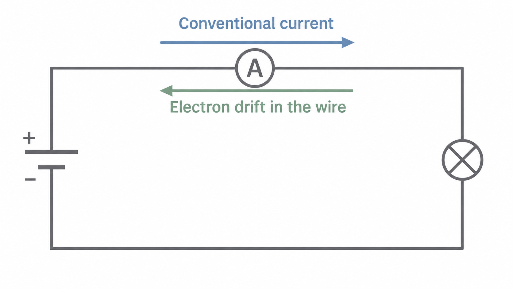
Conventional current follows the direction a positive charge would move: from the positive terminal through the external circuit to the negative terminal. Electron drift in a metal is opposite. The cell transfers energy to charges already present throughout the circuit; charge is not created at its positive terminal or consumed by the lamp.
[DIAGRAM: asset_name: 5.1.1 - Basics of Electricity - Diagram 1; asset_slug: 5.1.1 - Basics of Electricity - Diagram 1; caption: Conventional current and electron drift point in opposite directions along the same metal wire. The ammeter and lamp are in series.; description: Conventional current and electron drift point in opposite directions along the same metal wire. The ammeter and lamp are in series.]
A current of for transfers . Convert minutes to seconds before using an ampere value. If current varies, this equation gives the average current over the interval.
Potential difference is energy per charge
A component transfers energy when charge passes through a potential difference. Potential difference between two points is the work done or energy transferred per unit charge between them. A potential difference exists between points; current flows through a component.
Energy per charge
is in volts, in joules and in coulombs. .
A lamp with across it transfers for every coulomb passing through it. If passes, . The charge leaving the lamp has transferred energy; there is not less charge leaving than entering.
The same energy could be transferred by a larger charge moving through a smaller pd. For example, through also transfers . Energy alone therefore does not tell you the pd: the charge matters too.
Resistance and its measurement
The resistance of a component at an operating point is its pd divided by the current through it. In metals, electron scattering transfers energy to the lattice; different materials and devices need not share that same microscopic explanation.
Resistance
The equation defines resistance at the measured conditions. It does not assert that resistance stays constant as current, pd or temperature changes.
An ammeter goes in series in the current path. A voltmeter connects across the two ends of the component: it compares their potentials. Build the main loop first, then connect the voltmeter as a separate branch across the chosen component. Use a low supply setting initially and close the switch only when ready to measure.
[DIAGRAM: asset_name: 5.1.1 - Basics of Electricity - Diagram 2; asset_slug: 5.1.1 - Basics of Electricity - Diagram 2; caption: The ammeter is in the supply loop and the voltmeter connects to the two terminals of the test component. Treat both meters as ideal here.; description: The ammeter is in the supply loop and the voltmeter connects to the two terminals of the test component. Treat both meters as ideal here.]
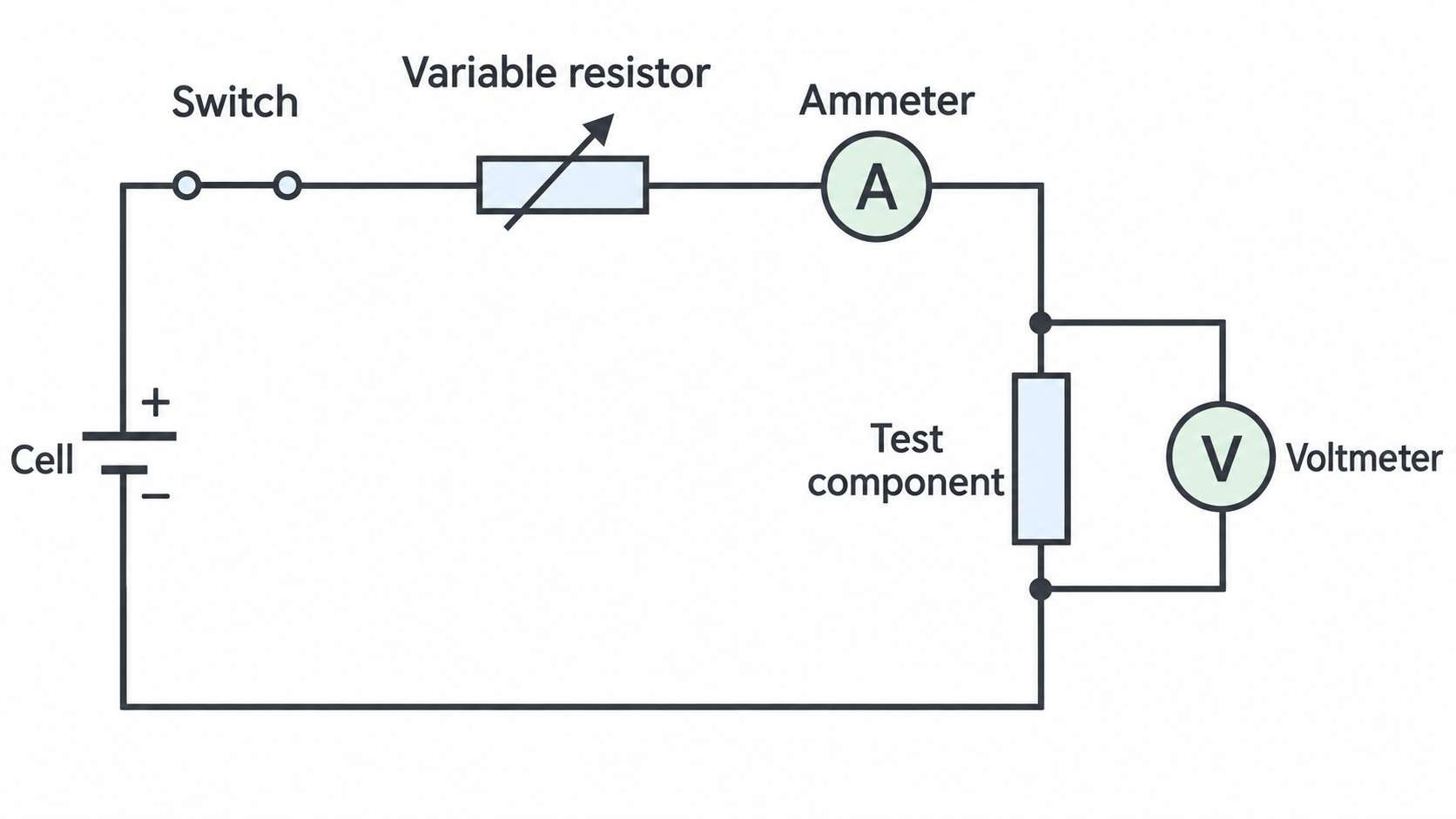
An ideal voltmeter takes no current, so the ammeter reading is the test-component current in this arrangement. A real voltmeter may take a small extra current; the ideal-meter assumption is examined in the next lesson. For and , .
Linking charge flow and energy transfer
The three definitions answer different questions about the same component. Resistance is determined by its operating pd and current. Charge and energy over an interval additionally depend on time. Doubling the operating time doubles charge and energy without, by itself, changing resistance.
A connected calculation
A component operates steadily at and for . First identify the required quantities:
The passes through the component and continues around the circuit. The is transferred from the electrical supply to other energy stores or radiation. The cell must replace the energy transferred on each complete journey; it does not replace used-up charge.
You can combine the last two equations as . This is useful when time, current and pd are supplied, but only if the chosen values describe the same component and interval. For a changing current or pd, a single initial reading does not necessarily describe the entire interval.