3.5.1.5 - Potential Divider
A potential divider supplies a fraction of a source pd. Derive that fraction, choose sensor positions for the required response, and check how a connected load changes the output.
Deriving the unloaded divider equation
A potential divider connects resistive components in series across a supply and takes an output between two points of the series combination. The output can be constant or can change with a variable resistance. Identify its two connection points before calculating it.
[DIAGRAM: asset_name: 5.1.5 - Potential Divider - Diagram 1; asset_slug: 5.1.5 - Potential Divider - Diagram 1; caption: An unloaded divider across a fixed input pd. The output is connected across the lower resistor only.; description: An unloaded divider across a fixed input pd. The output is connected across the lower resistor only.]
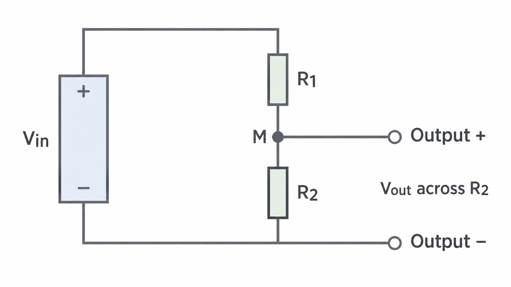
With no appreciable current taken by the output, both resistors carry . Multiplying by the output resistor gives
The pd across is , so . An ideal voltmeter does not change this reasoning because it takes no current.
For , and , . The other resistor has . Using kilohms consistently in the ratio is valid; calculating current requires conversion to ohms, giving .
Multiplying both resistances by the same factor leaves the unloaded output unchanged but reduces supply current. The output stays between zero and the input for positive resistances. The numerator is always the resistance across the output, not automatically the sensor or lower-valued resistor.
Varying output with a resistor or sliding contact
Changing either resistance changes the division of pd. With output across a fixed , increasing a variable reduces current and output. With output across the variable resistor instead, its increasing resistance gives it a larger fraction of the input.
A sliding-contact divider uses the two portions of one resistive track. Connect the track ends across the source and take the output between the slider and one chosen end. This three-terminal arrangement differs from using two terminals as a simple series rheostat.
[DIAGRAM: asset_name: 5.1.5 - Potential Divider - Diagram 2; asset_slug: 5.1.5 - Potential Divider - Diagram 2; caption: A sliding contact selects a portion of a uniform wire. The output magnitude between A and P depends on their separation x. The wire ends span the source pd.; description: A sliding contact selects a portion of a uniform wire. The output magnitude between A and P depends on their separation x. The wire ends span the source pd.]
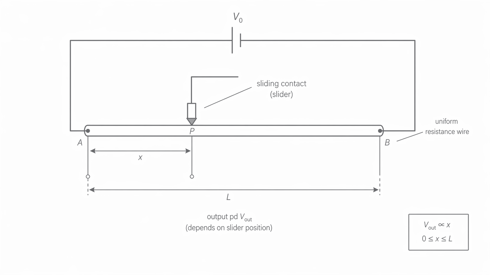
For a uniform wire of length with negligible output current, resistance is proportional to length. An output across length has
The output magnitude is zero when slider and reference end coincide and equals the full input at the other end. If , and , the output is .
A finite series rheostat with a lamp cannot reduce the lamp’s pd exactly to zero while a closed conducting path remains. A sliding divider can reach the zero endpoint by connecting both output leads to the same node. With a load attached, the intermediate output is generally not proportional to slider position: the load changes the resistance ratio. The use of a potentiometer as a measuring instrument is not required here.
Choosing the response of a thermistor or LDR divider
An NTC thermistor decreases in resistance as temperature rises. An LDR decreases in resistance as illumination increases. A divider turns these changes into an electrical signal; the output connections determine the sign of the response.
[DIAGRAM: asset_name: 5.1.5 - Potential Divider - Diagram 3; asset_slug: 5.1.5 - Potential Divider - Diagram 3; caption: The NTC thermistor is above the fixed resistor. Output across the fixed resistor increases when the thermistor warms. Assume negligible output current.; description: The NTC thermistor is above the fixed resistor. Output across the fixed resistor increases when the thermistor warms. Assume negligible output current.]
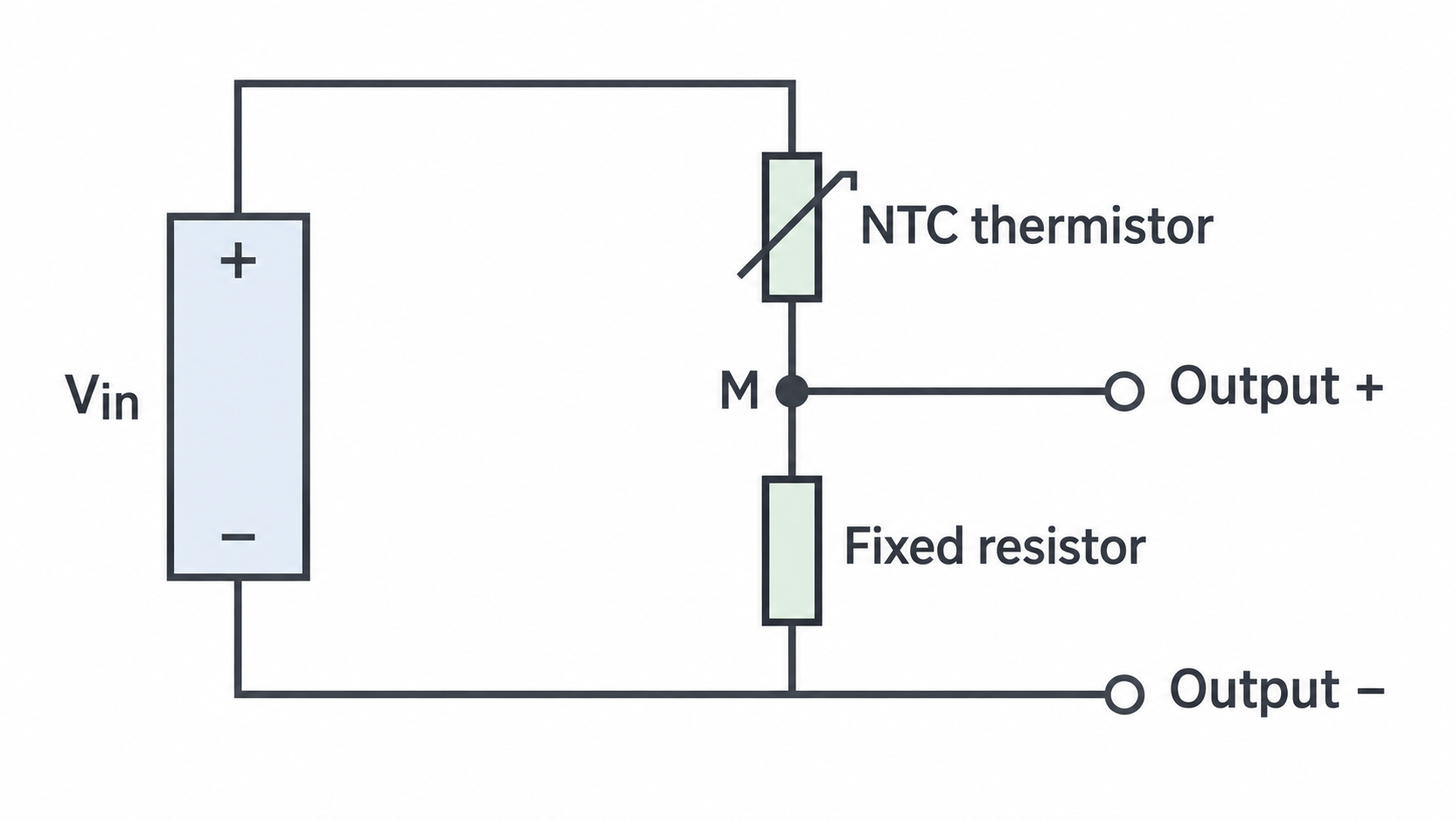
With a sensor resistance and fixed resistance , output across the fixed resistor is . When falls, total resistance falls and current rises. Since stays fixed, its pd rises. Output across the sensor instead is , which falls as falls. “Current rises, so every pd rises” is wrong: the sensor resistance also changes.
Continue this lesson.
You’re previewing NovaLearn without an account. Create a free account to read the rest.
Create free account