3.7.4.4 - Capacitor Charge and Discharge
Explain how resistor–capacitor circuits change with time, use charging and discharging equations, and determine time constants from curve shape, tangents and logarithmic plots.
Charging through a resistor
An initially uncharged capacitor connected in series with a resistor and a constant-voltage supply starts with zero capacitor pd. The initial current is therefore , because the full source pd is across the resistor.
[DIAGRAM: asset_name: 7.4.4 - Capacitor Charge and Discharge - Diagram 1; asset_slug: 7.4.4 - Capacitor Charge and Discharge - Diagram 1; caption: The switch is shown open. After it closes, conventional charging current flows from the cell positive terminal through R towards the upper capacitor plate, which becomes positive.; description: The switch is shown open. After it closes, conventional charging current flows from the cell positive terminal through R towards the upper capacitor plate, which becomes positive.]
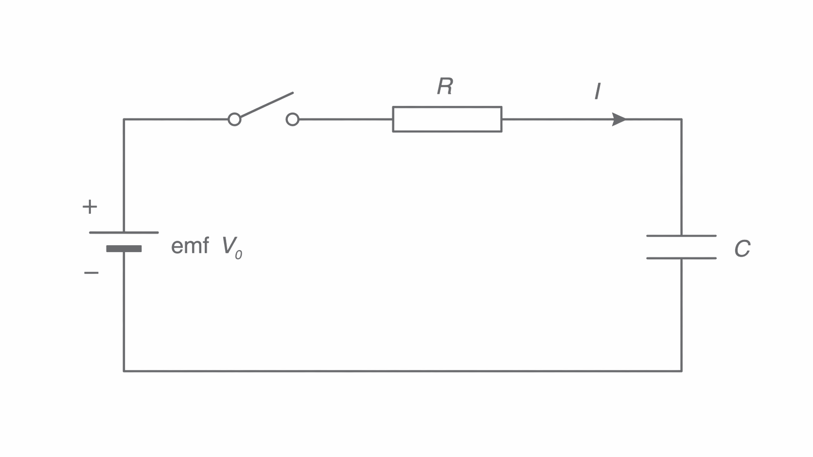
As charge separates, rises. Kirchhoff's voltage law gives : the resistor pd falls, so current falls even though is constant. Electrons move through the wires, never across the capacitor's intact dielectric. The ideal final state has , and zero current, approached asymptotically.
Initially uncharged capacitor
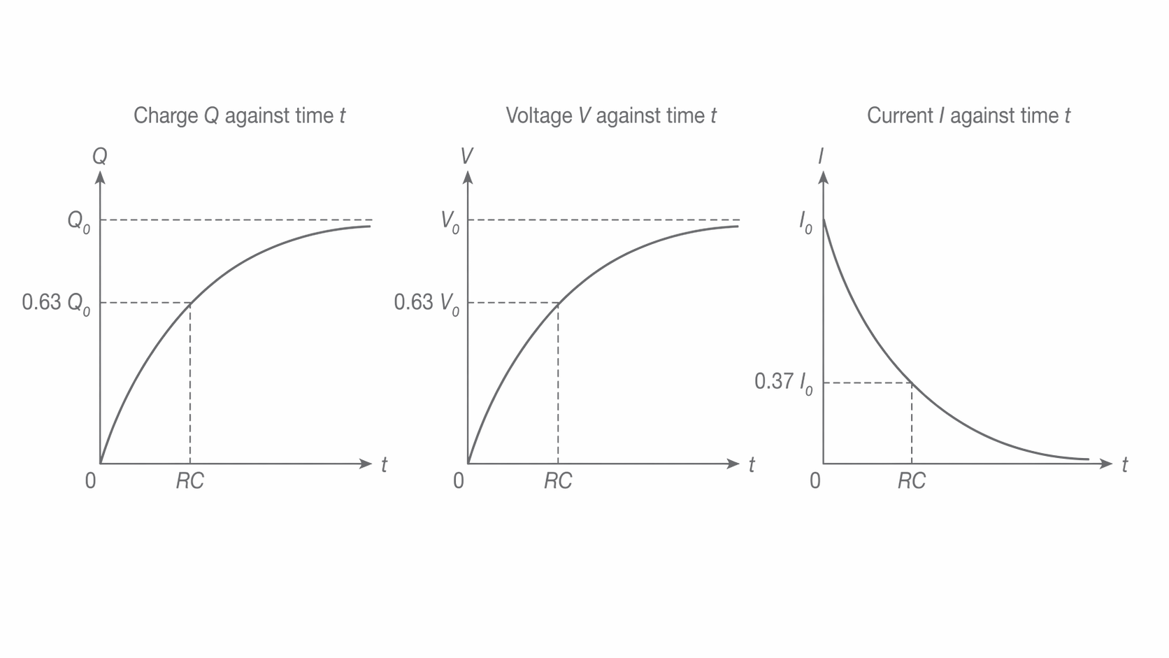
Here is the switch-closing instant, and remain constant. Notice that current decreases while charge and capacitor pd increase.
[DIAGRAM: asset_name: 7.4.4 - Capacitor Charge and Discharge - Diagram 2; asset_slug: 7.4.4 - Capacitor Charge and Discharge - Diagram 2; caption: Charging Q and V rise towards their final values while current falls. In this graph Q0 denotes final charge and V0 the source pd, at t = RC the fractions are 0.63, 0.63 and 0.37.; description: Charging Q and V rise towards their final values while current falls. In this graph Q0 denotes final charge and V0 the source pd, at t = RC the fractions are 0.63, 0.63 and 0.37.]
Discharge, current direction and sign
A charged capacitor discharges when the supply is disconnected and a resistor completes a loop between its plates. Conventional current flows externally from the positive plate through the resistor to the negative plate. Electrons move oppositely, reducing the excess electrons on the negative plate and replenishing those missing from the positive plate.
[DIAGRAM: asset_name: 7.4.4 - Capacitor Charge and Discharge - Diagram 3; asset_slug: 7.4.4 - Capacitor Charge and Discharge - Diagram 3; caption: Supply-free discharge loop. The upper capacitor plate is initially positive and the lower plate negative, so the illustrated clockwise arrow is conventional discharge current.; description: Supply-free discharge loop. The upper capacitor plate is initially positive and the lower plate negative, so the illustrated clockwise arrow is conventional discharge current.]
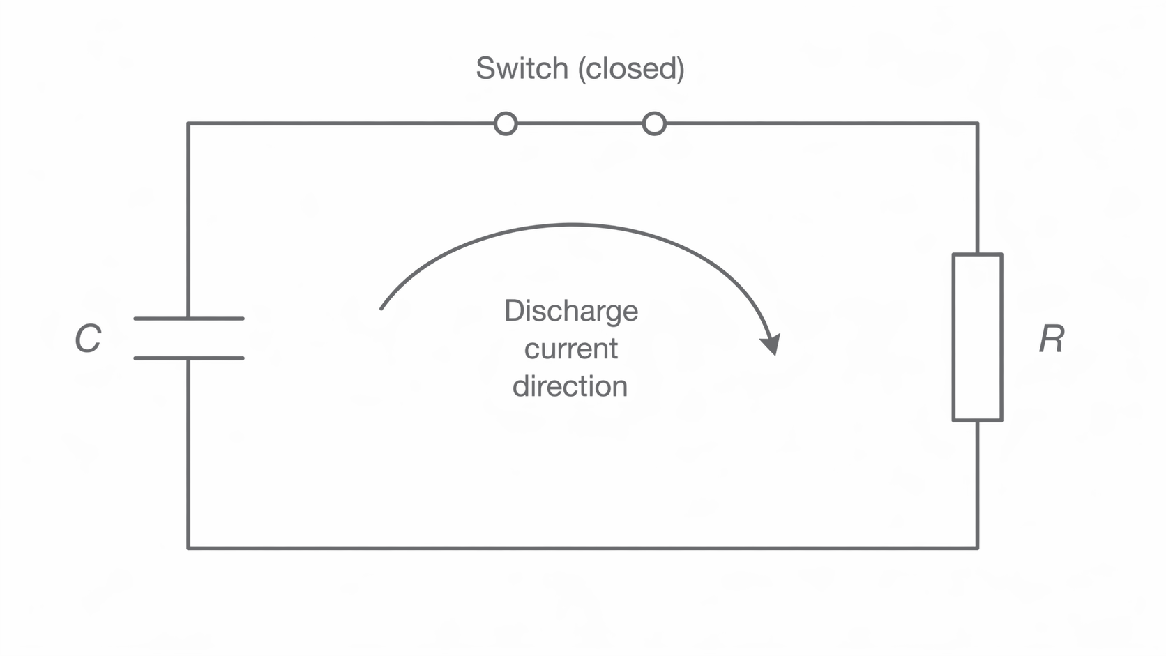
Let be the positive magnitude of charge remaining, and the positive magnitude of discharge current. Since and ,
The rate of charge loss is proportional to remaining charge. That gives exponential decay: the same fraction is lost in equal time intervals, not the same amount.
Discharge from Q0 and V0
[DIAGRAM: asset_name: 7.4.4 - Capacitor Charge and Discharge - Diagram 4; asset_slug: 7.4.4 - Capacitor Charge and Discharge - Diagram 4; caption: During discharge, charge remaining, capacitor pd and discharge-current magnitude all fall exponentially. Each is 0.37 of its initial value after one time constant.; description: During discharge, charge remaining, capacitor pd and discharge-current magnitude all fall exponentially. Each is 0.37 of its initial value after one time constant.]
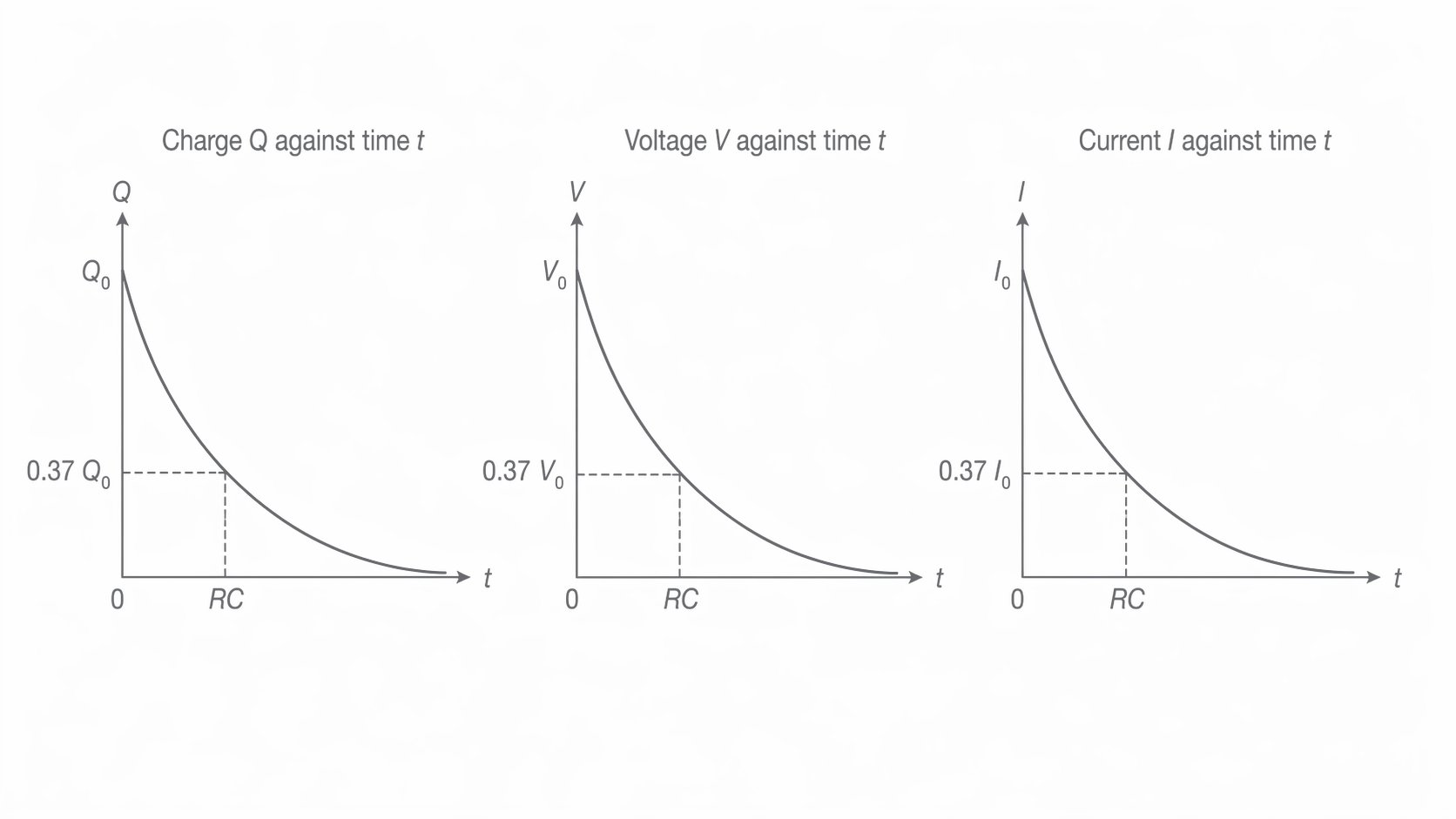
These graphs show positive magnitudes. If a fixed current sign convention is chosen as positive into the plate that becomes positive on charging, discharge current is negative: . Its signed graph rises from a negative value towards zero. Reversing a current arrow changes the sign convention, not the physics; compare directions at the same capacitor terminal, not clockwise labels on differently drawn circuits.
Time constant and tangent construction
The time constant measures how quickly the circuit changes. Its units are seconds because . Larger reduces current for a given pd; larger requires more charge for a given pd change. Either makes the response slower.
At , . A discharge quantity falls to 36.8% of its starting value, while charging or rises to 63.2% of its final value. Charging current falls to 36.8% of its initial value. After , only , or 0.674%, of the original discharge quantity remains. 'Fully charged' or 'fully discharged' is a practical approximation.
Continue this lesson.
You’re previewing NovaLearn without an account. Create a free account to read the rest.
Create free account