3.7.5.1 - Magnetic Flux Density
A current-carrying wire can experience a force in an external magnetic field. The field strength, current, active wire length and orientation determine that force. This lesson separates its magnitude from its direction, then uses the force to measure a field or support a load.
The field around a current-carrying wire
A straight current-carrying wire produces circular magnetic field lines centred on the wire. A compass north pole points along the local field direction: outside a bar magnet, this is from north to south. Field lines describe a direction at each point; they are not physical threads.
Use the right-hand grip rule for the field produced by the wire: point your right thumb along conventional current and curl your fingers around the wire. The fingers give the field direction. Looking down onto a wire whose current points towards you, the field goes anticlockwise. Reverse the current and every field arrow reverses. The field becomes weaker farther from the wire.
[DIAGRAM: asset_name: 7.5.1 - Magnetic Flux Density - Diagram 1; asset_slug: 7.5.1 - Magnetic Flux Density - Diagram 1; caption: Circular magnetic field around an upward conventional current; description: A straight wire with concentric field lines. Use the right-hand grip rule to interpret the perspective view.]
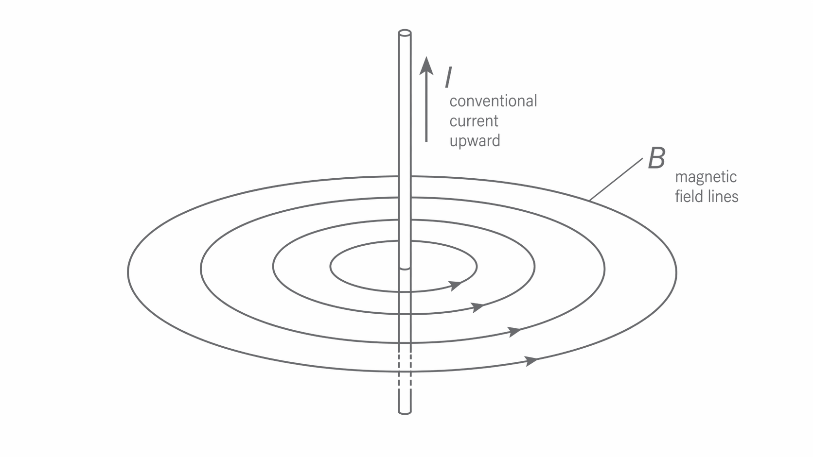
Do not confuse this circular field of the wire with the external field applied by a magnet. The motor effect is a force on the wire due to that external field. A parallel wire has no magnetic force even though it carries current and produces its own field. The grip rule finds a field direction; Fleming's left-hand rule, introduced later, finds a force direction.
Defining magnetic flux density and the tesla
Magnetic flux density measures the strength of a magnetic field. For a straight length carrying current perpendicular to a uniform field, it is defined by the force per unit current per unit length:
One tesla, , is the flux density that produces a force of on of wire carrying perpendicular to the field. Thus
The perpendicular condition belongs in the definition: a wire parallel to even a strong field has zero force. The current and length are properties of the probe wire, not of the field. Doubling the current doubles the force, leaving the calculated unchanged.
Calculating the force and choosing the active length
For a straight wire perpendicular to a uniform magnetic field, the force magnitude is
Use tesla, ampere and metre to obtain newtons. With the other quantities fixed, is directly proportional to , and . Here is the length inside the field, not the total length of connecting wire. A wire with only in the uniform gap uses .
If the field has a component parallel to the wire, that component gives no force. Use only the perpendicular component in . For example, a vertical wire carrying downwards through has a horizontal field component of due north and a vertical component of . Only the horizontal component contributes:
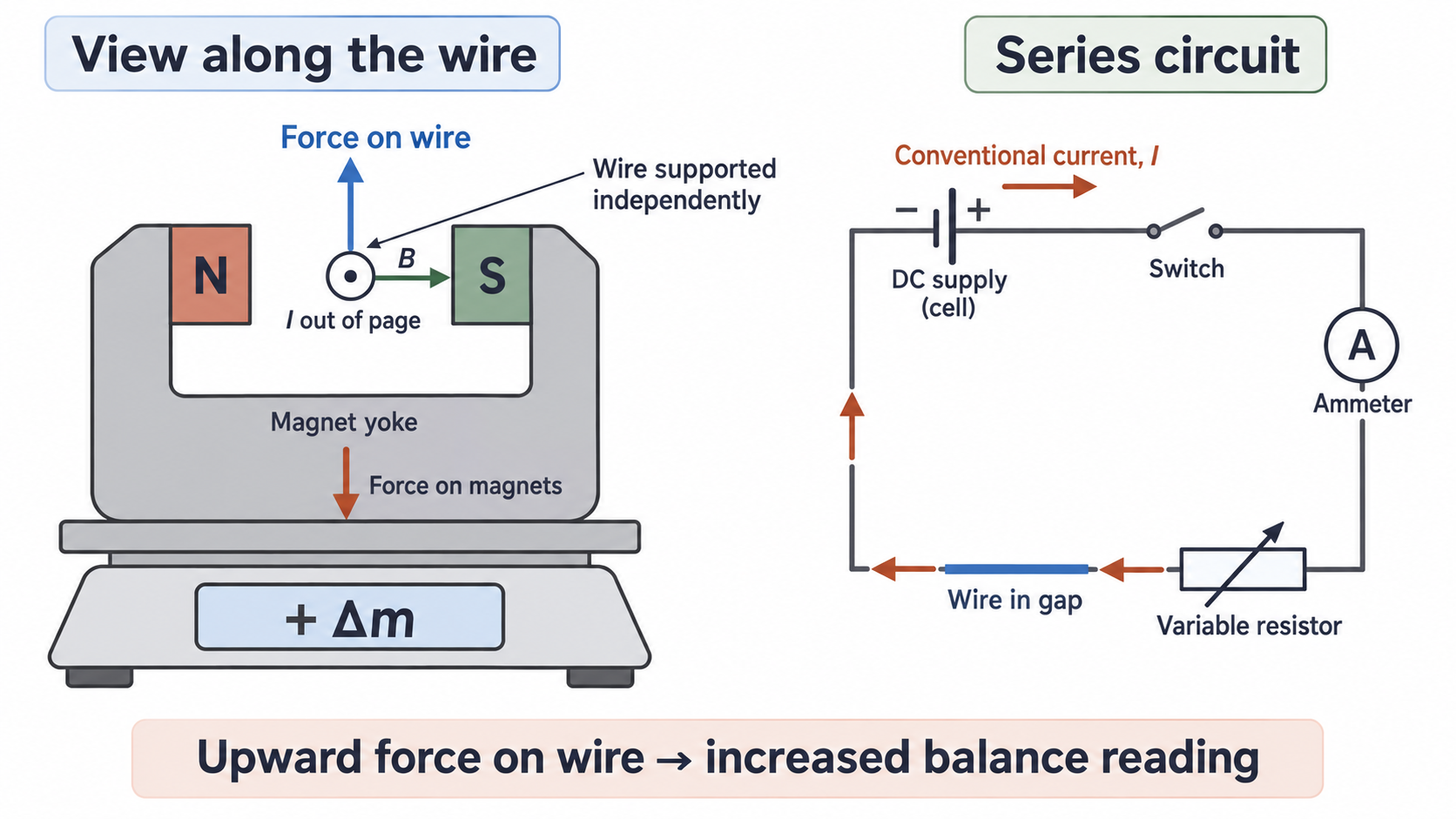
A top-pan balance can measure the motor effect indirectly. Support the wire separately and place the magnets on the balance. An upward magnetic force on the wire has an equal downward reaction force on the magnets, increasing the balance reading. If the signed mass change is , the force magnitude is , with mass in kilograms. A decrease is also a measurable magnetic force.
[DIAGRAM: asset_name: 7.5.1 - Magnetic Flux Density - Diagram 2; asset_slug: 7.5.1 - Magnetic Flux Density - Diagram 2; caption: Independent wire and magnet supports reveal the magnetic reaction force; description: End-on view of current out of the page in a rightward field. The wire force is up and the magnet force down. The separate series circuit controls current.]
Continue this lesson.
You’re previewing NovaLearn without an account. Create a free account to read the rest.
Create free account