3.7.5.4 - Electromagnetic Induction
Use observations, signed flux changes and energy conservation to explain induction, then calculate the emf produced by moving rods and rotating coils.
When a changing field produces emf
A magnet pushed into a coil connected to a sensitive centre-zero meter produces a deflection. Hold the magnet still and the reading returns to zero; pull it out and the deflection reverses. Faster motion produces a larger deflection. Reverse the magnet's poles and the deflections reverse. These observations point to changing magnetic flux linkage, rather than a magnetic field by itself, as the cause of induction.
An induced emf is energy transferred per unit charge by the induction process. It can exist across the ends of an open conductor. An appreciable induced current requires a closed conducting path; its size also depends on circuit resistance. Opening a coil does not stop the induced emf, but it stops the circulating current and greatly reduces its magnetic braking effect.
A stationary coil also develops an emf if a nearby electromagnet's current changes: motion is one way to change flux, not a requirement. The change can be in field strength, area within the field or angle to the field.
For a straight rod, moving charges feel a magnetic force. In the diagram, the rod moves right and the field points into the page. Positive charges would be pushed up; electrons move down, leaving the top positive. In an isolated rod, charge separation produces an electric field until electric and magnetic forces balance.
[DIAGRAM: asset_name: 7.5.4 - Electromagnetic Induction - Diagram 1; asset_slug: 7.5.4 - Electromagnetic Induction - Diagram 1; recommended_method: local_png; caption: A vertical rod moving right through a field into the page: electrons are forced down, leaving the top positive and bottom negative.; description: A vertical rod moving right through a field into the page: electrons are forced down, leaving the top positive and bottom negative.]
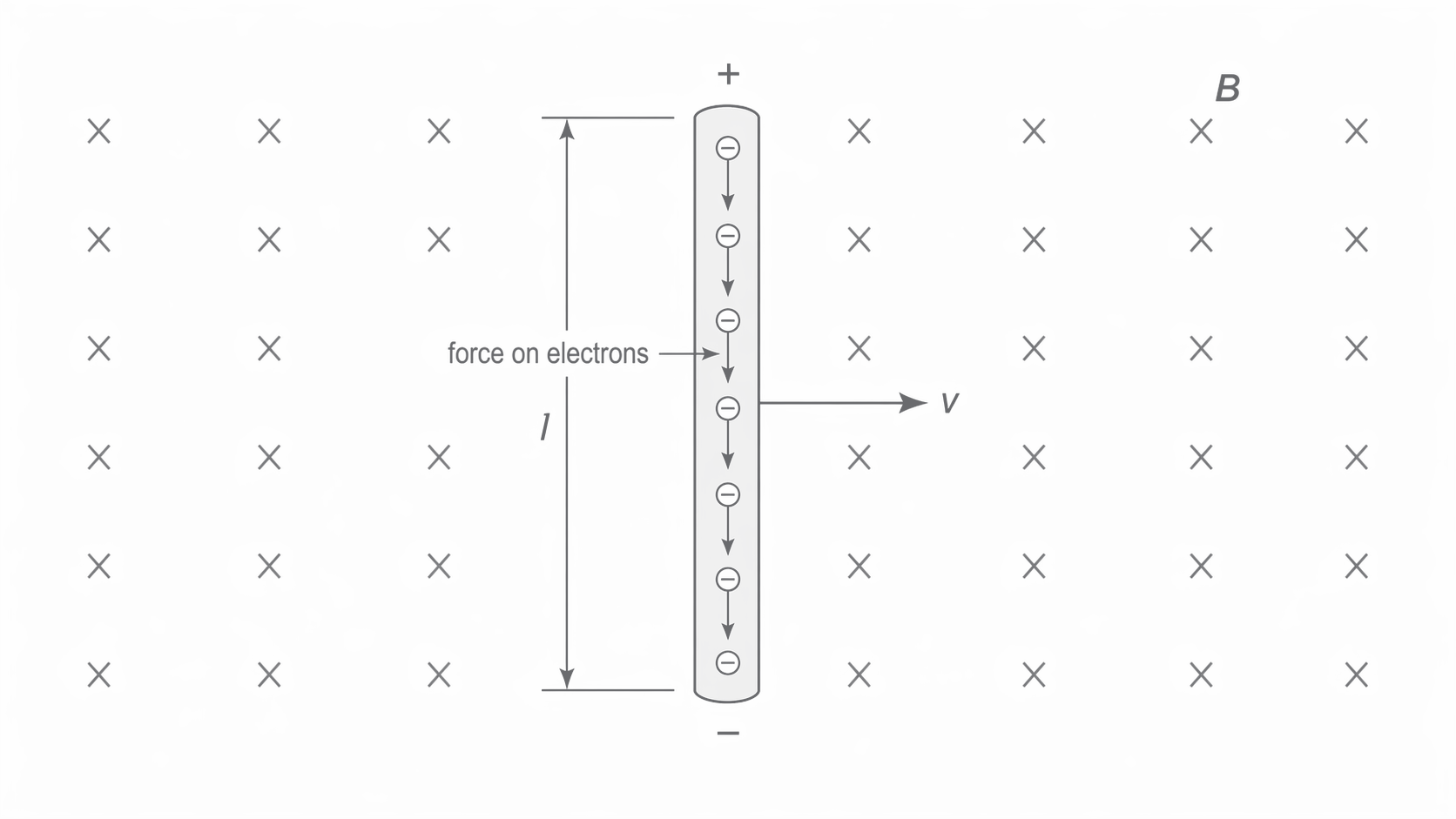
Fleming's right-hand rule gives the conventional-current direction for the generator geometry: first finger along the field, thumb along motion, second finger along induced conventional current. The three directions are perpendicular. If motion is parallel to the field there is no magnetic force on the moving charges. Even with motion perpendicular to the field, the rod must have a component along the force direction to develop an emf between its ends.
Faraday's law and signed flux change
Faraday's law relates induced emf to the rate of change of flux linkage. Write flux linkage as . For a uniform field through each turn, , where is measured from the normal to the coil plane. Flux and flux linkage have units ; the number of turns is dimensionless.
Average and instantaneous emf
For magnitudes use . A finite change divided by time gives an average signed emf; it gives the instantaneous emf only when the slope is constant. On a flux-linkage–time graph, the emf is the negative gradient. A horizontal tangent means zero emf even if the flux linkage is large.
To use signs consistently, choose a positive normal through the coil. The positive direction around the circuit follows curled right-hand fingers when the thumb points along that normal. With these paired choices, increasing positive linkage gives negative emf. Reversing both reference directions changes the signs but not the physics.
A reversal is a change of twice the initial linkage
A -turn coil of area is reversed in a field. Its linkage changes from to , so . If reversal takes , the average signed emf is . Its peak value cannot be inferred without knowing how the coil rotates during that time.
Lenz's law and energy transfer
Lenz's law says the induced emf drives a current whose magnetic effect opposes the change in flux linkage producing it. It does not mean the induced field always points opposite to the original field: when the original flux decreases, the induced field acts to maintain it.
Consider a bar magnet falling north pole first through a closed horizontal coil. Ignore the coil's self-inductance in this simple demonstration, so current follows emf. Viewed from above:
- On approach, the downward flux increases. An upward induced field opposes that increase. The current is anticlockwise and the top of the coil behaves as a north pole, repelling the approaching north pole.
- When the magnet is centred symmetrically, the linkage is at an extremum and its instantaneous rate of change is zero. The emf and, in this resistive approximation, current are momentarily zero.
- On departure, downward flux decreases. The current reverses to clockwise, producing a downward field. The bottom of the coil is now a north pole and attracts the magnet's receding south pole.
[DIAGRAM: asset_name: 7.5.4 - Electromagnetic Induction - Diagram 2; asset_slug: 7.5.4 - Electromagnetic Induction - Diagram 2; recommended_method: local_png; caption: North-first falling magnet: the current is anticlockwise viewed from above on approach and clockwise on departure, the magnetic force opposes motion in both cases.; description: North-first falling magnet: the current is anticlockwise viewed from above on approach and clockwise on departure; the magnetic force opposes motion in both cases.]
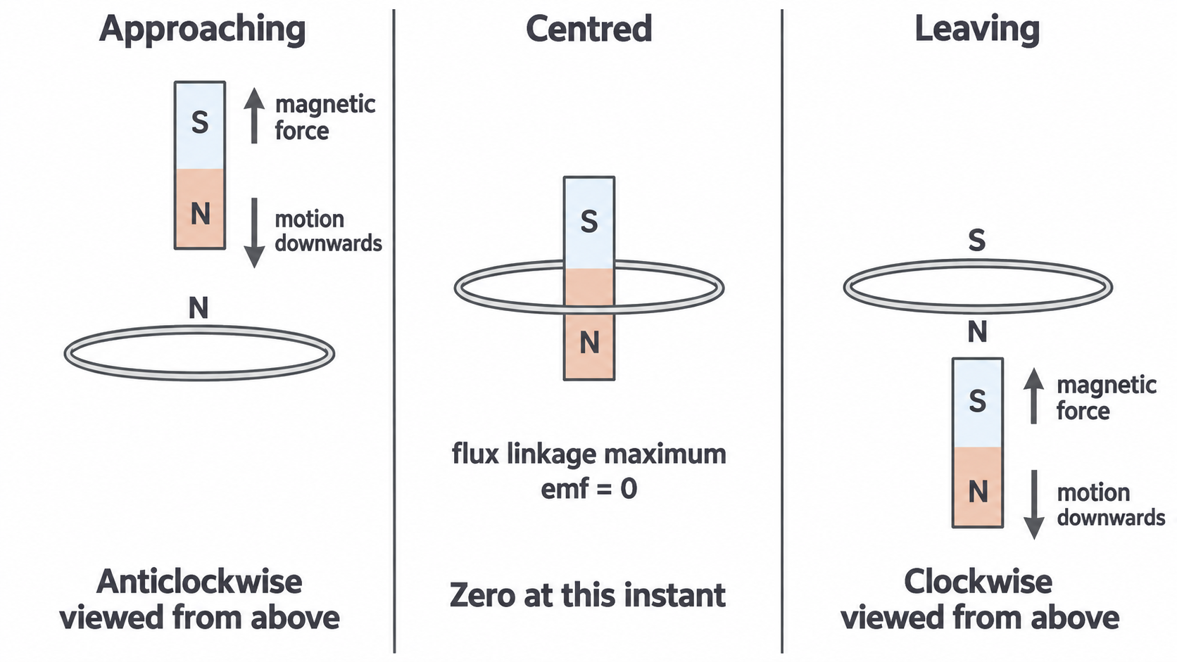
In both moving stages the magnetic force is upward. Some of the decreasing gravitational potential energy is transferred to thermal energy in the coil or resistor, so less becomes kinetic energy. If induced current instead reinforced the motion, the magnet would gain extra mechanical energy while also heating the resistor with no corresponding energy source. The opposition required by Lenz's law ensures conservation of energy.
Continue this lesson.
You’re previewing NovaLearn without an account. Create a free account to read the rest.
Create free account