3.13.1.3 - Photodiode
Light produces a current in a photodiode. Learn to read its electrical and spectral characteristics, trace the output of a reverse-biased detector and follow the signal from optical pulses or a scintillator.
From absorbed photons to current
A photodiode turns incident light into an electrical signal. Photons absorbed at or near its p–n junction can create electron–hole pairs, provided they have enough energy for that semiconductor.
The junction's electric field separates the carriers: electrons move toward the N-type side and holes toward the P-type side. With an external circuit connected, this produces current. At a fixed wavelength and within the detector's working range, a greater incident optical power means more absorbed photons per second and a greater photocurrent.
[DIAGRAM: asset_name: E.1.3 - Photodiode - Diagram 1; asset_slug: E.1.3 - Photodiode - Diagram 1; caption: Photon-generated carriers in a reverse-biased junction; description: Reverse-biased photodiode cross-section: photons create pairs, holes move toward the negative P side and electrons toward the positive N side.]
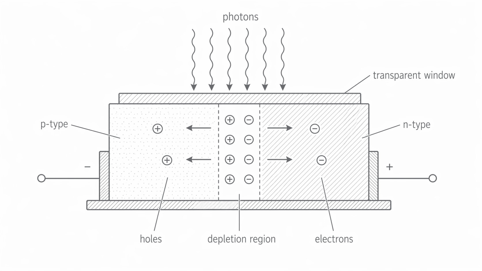
A small dark current flows under reverse bias even when no light falls on the diode, because charge carriers are also generated thermally. The measured reverse-current magnitude is approximately the dark-current magnitude plus the photocurrent magnitude. Dark current is a baseline, not evidence of light. Temperature changes and electrical noise can limit the detection of weak signals.
For example, a measured current of with a dark reading of corresponds to a light-produced current of . Subtract dark current when finding photocurrent from a reading; add it when predicting the total reading.
Reverse bias and the direction of the signal
In photoconductive mode, the cathode is held more positive than the anode, so the photodiode is reverse biased. Reverse bias supports a short response time and an approximately linear relation between photocurrent and illumination over the working range. A short response lets successive light pulses produce distinguishable electrical pulses.
The graph uses anode-minus-cathode voltage and conventional current from anode to cathode as positive. Reverse current is therefore negative. “The current increases with light” means its magnitude increases: on these signed axes the illuminated curves move downwards.
[DIAGRAM: asset_name: E.1.3 - Photodiode - Diagram 2; asset_slug: E.1.3 - Photodiode - Diagram 2; caption: Illumination shifts the signed photodiode current; description: Illustrative signed photodiode I–V curves at fixed wavelength: illumination moves reverse current downwards, with nonzero short-circuit photocurrent at zero applied voltage.]
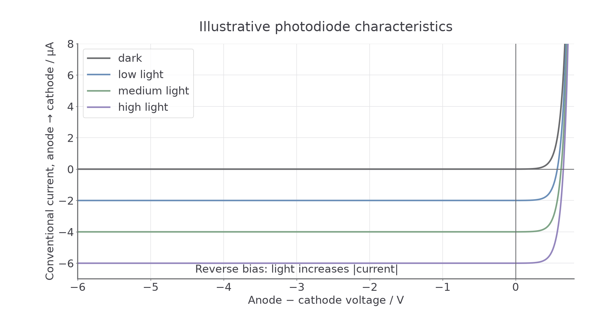
At fixed illumination and away from breakdown, the reverse-bias branch is almost horizontal: changing reverse voltage has little effect on the photocurrent. At fixed reverse voltage, changing illumination changes the current strongly. The illuminated curves need not pass through the origin; light can also generate a signal with no external bias, called photovoltaic operation. Here the detector is deliberately operated in reverse bias.
To convert current to voltage, connect the cathode toward a positive supply and the anode through a resistor to . Measure the anode's potential relative to .
[DIAGRAM: asset_name: E.1.3 - Photodiode - Diagram 6; asset_slug: E.1.3 - Photodiode - Diagram 6; caption: Output across a resistor rises with the photocurrent; description: Reverse-biased photodiode current flows from the positive supply through the diode and resistor to 0 V; the output across the resistor rises with light.]
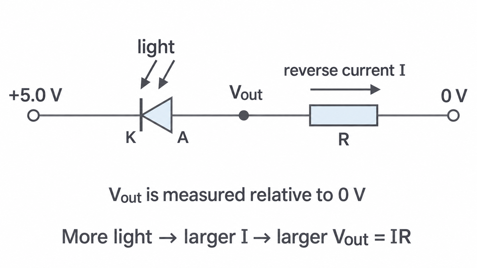
In this arrangement . More light gives a larger reverse-current magnitude, hence a higher positive output. Meanwhile the reverse p.d. across the diode is , which becomes smaller. The relation holds while the diode remains suitably reverse biased and the output is not significantly loaded. If a circuit takes its output at a different node or uses an inverting amplifier, the voltage can change in the opposite direction: always trace the actual circuit.
For and , . On a supply, the diode still has reverse bias.
Choosing a detector for a wavelength
A photodiode's sensitivity depends on wavelength as well as incident power. Its responsivity is the photocurrent per unit incident optical power at a specified wavelength:
Responsivity has unit . Use optical power reaching the sensitive area, not a source's total emitted power. If irradiance is given in , the power on a uniformly illuminated area is .
Continue this lesson.
You’re previewing NovaLearn without an account. Create a free account to read the rest.
Create free account