3.4.1.1 - Scalars and Vectors
Describe magnitude and direction, build resultants, resolve forces and test equilibrium. The same vector methods apply to displacement, velocity and force, but a force diagram must represent the actual forces on one object.
Scalars and vectors
A scalar has magnitude only; a vector has magnitude and direction. Direction affects how vectors combine, so two equal forces can cancel while two equal masses cannot.
| Scalars | Vectors |
|---|---|
| Distance, speed | Displacement, velocity |
| Mass | Force, including weight |
| Time, temperature, energy | Acceleration, momentum |
Speed is the magnitude of instantaneous velocity. Distance is the length of the path; displacement is the change in position from start to finish. Walking east then west gives a distance of and zero displacement. Distance equals displacement magnitude only for a straight journey with no reversal.
Represent a vector by an arrow: length represents magnitude and the arrowhead gives direction. Choose and state positive axes. A westward velocity can be negative when east is positive; a negative component describes direction, not a negative speed.
Resultants of perpendicular vectors
The resultant is the single vector equal to the vector sum. Along one line, use signed addition: right and left give right. For perpendicular components, build a right-angled triangle.
Here is measured from the positive direction towards . Choose the physical quadrant from the signs; an inverse tangent alone does not describe the direction fully.
[DIAGRAM: asset_name: 4.1.1 - Scalars and Vectors - Diagram 1; asset_slug: 4.1.1 - Scalars and Vectors - Diagram 1; recommended_method: retained_png; caption: The resultant R runs from the first tail to the final tip, A and B are perpendicular.; description: The resultant R runs from the first tail to the final tip, A and B are perpendicular.]
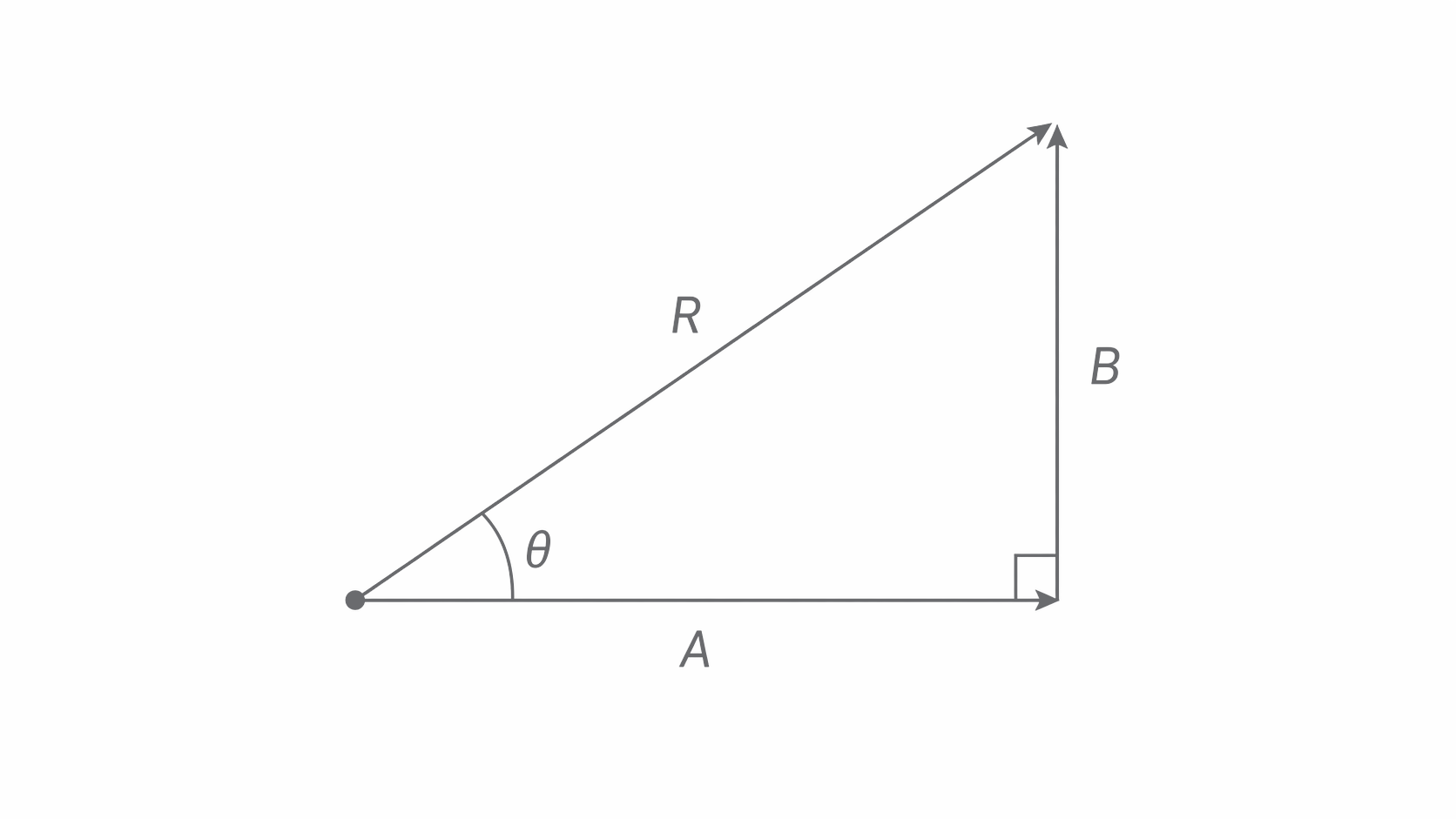
For east and north, and north of east. Pythagoras applies because the angle is , not simply because there are two vectors.
Reduce a 3D frame to two right triangles
A perspective sketch of a cube does not preserve its angles on the page. To find the true direction of a cable through a regular 3D structure, identify a plane containing the cable and a known perpendicular direction.
A cube-shaped frame has side length . A straight cable joins a lower corner O to the diagonally opposite upper corner Q. Let P be the base corner vertically below Q. The horizontal line OP is a base diagonal, not a base edge. In the square base, its two perpendicular edge components each have length , so
PQ is vertical and perpendicular to the whole horizontal base, so it is perpendicular to OP. The vertical section OPQ is therefore a right triangle even though OP runs diagonally across the base.
[DIAGRAM: asset_name: vectors-3d-cable; asset_slug: vectors-3d-cable; recommended_method: matplotlib; caption: A cube-frame cable and its true vertical section OPQ. The base diagonal OP is perpendicular to the vertical edge PQ.; description: A cube-frame cable and its true vertical section OPQ. The base diagonal OP is perpendicular to the vertical edge PQ.]
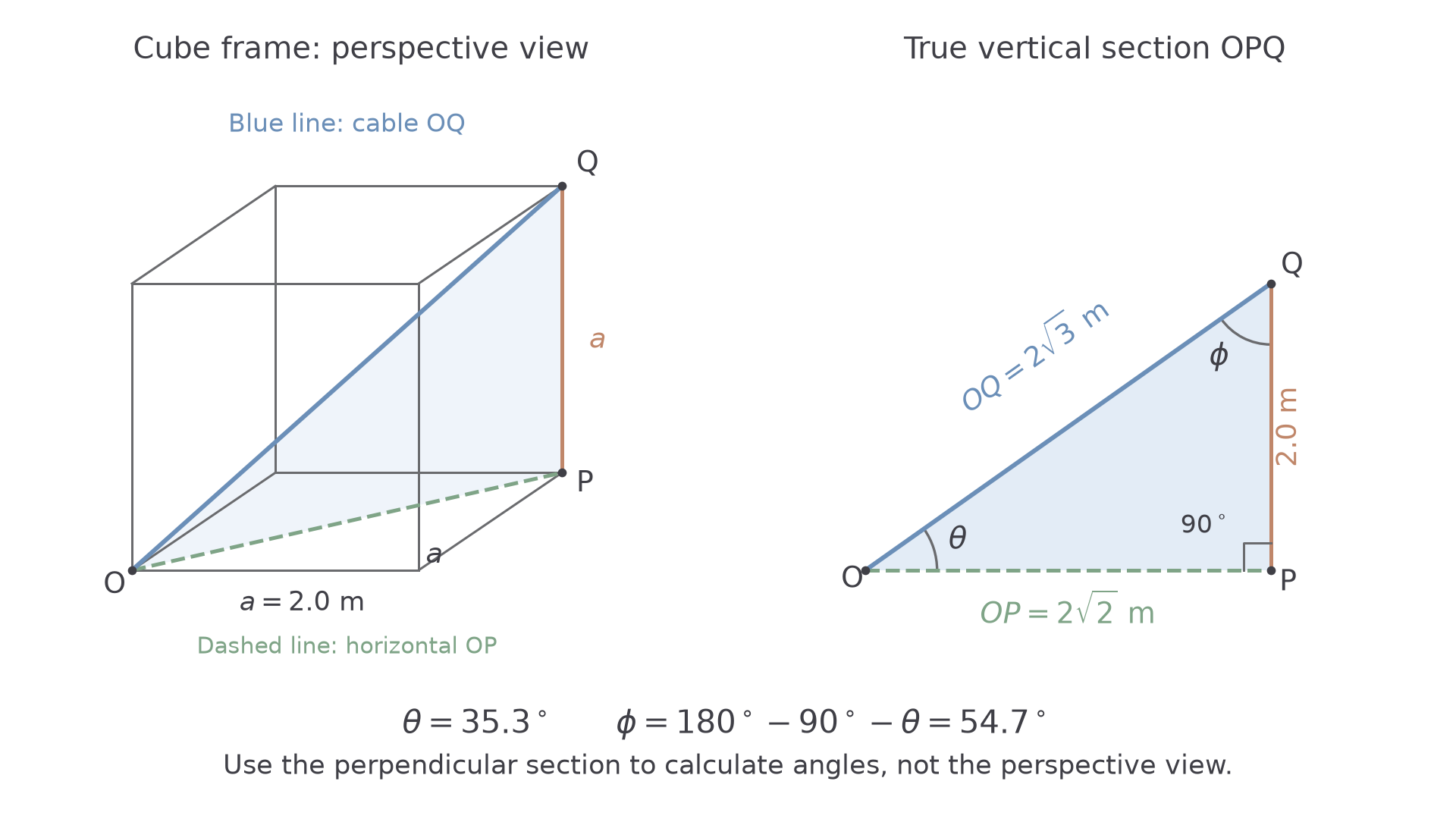
Apply Pythagoras again in this section:
The cable is long. Its angle above the horizontal base is the angle between OQ and its horizontal projection OP:
Thus . It is not : the horizontal side of this triangle is the longer base diagonal, not a cube edge.
The interior angles of a triangle add to . In OPQ, the angle at P is , so the remaining acute angle between the cable and the vertical satisfies
Therefore , the cable's angle to a vertical edge, without another inverse-trigonometric calculation. A tension force along the cable has the same line of action. For a rectangular frame, use the actual two base-edge lengths to find OP, then combine OP with the height in the same perpendicular section; never read the true angle from the perspective sketch.
Scale drawings and non-perpendicular vectors
A scale construction handles directions that are not perpendicular. Choose a large enough scale to measure reliably, state it, and use a ruler and protractor. For example, could represent .
Draw the first force to scale. Translate the second arrow so its tail begins at the first tip, without rotating it. The resultant runs from the original tail to the final tip. Measure its length, convert using the scale, then measure and state its angle from a named direction. A parallelogram construction from a common tail gives the same resultant.
[DIAGRAM: asset_name: 4.1.1 - Scalars and Vectors - Diagram 2; asset_slug: 4.1.1 - Scalars and Vectors - Diagram 2; recommended_method: retained_png; caption: OA followed by AB gives OB. Translating an arrow preserves its magnitude and direction.; description: OA followed by AB gives OB. Translating an arrow preserves its magnitude and direction.]
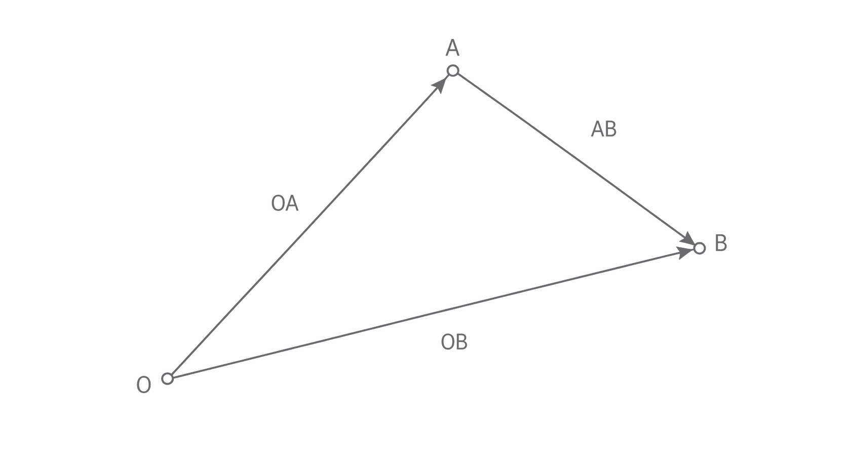
For a journey of on a bearing of , followed by due east, a scale drawing gives about on a bearing of . Bearings are measured clockwise from north. The resultant is not : the two displacements are not parallel.
Drawing precision limits the result. A reading difference at a scale of corresponds to . The online questions ask you to describe or interpret a construction; practise the actual drawing on paper.
Resolving into chosen axes
Resolving replaces a vector by two perpendicular components whose sum is the original vector. The components are not extra forces to add to the original force. Draw either the force itself or its resolved components in an equation, without double-counting.
For a vector at angle above the horizontal,
Cosine gives the side adjacent to the stated angle. If the angle is measured from the vertical, interchange the roles of sine and cosine. Assign signs using the chosen axes.
[DIAGRAM: asset_name: 4.1.1 - Scalars and Vectors - Diagram 3; asset_slug: 4.1.1 - Scalars and Vectors - Diagram 3; recommended_method: retained_png; caption: The horizontal component is adjacent to θ, the vertical component is opposite.; description: The horizontal component is adjacent to θ, the vertical component is opposite.]
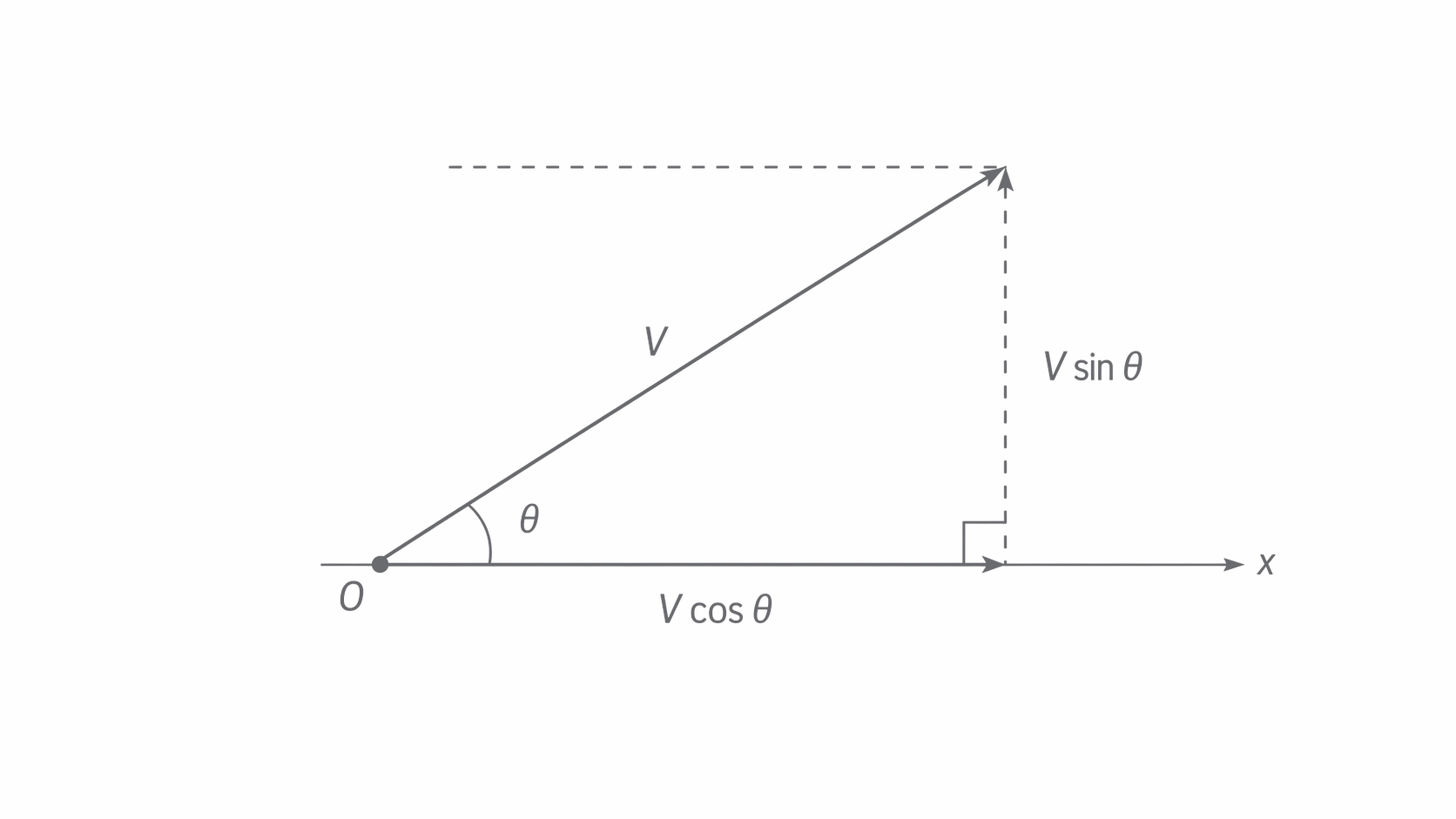
A force at below the positive horizontal has components and , with upward positive.
Weight on an inclined plane
Choose axes down the plane and into the plane. For a slope inclined at to the horizontal, the angle between vertically downward weight and the inward perpendicular is also : both reference directions have rotated through the slope angle. Therefore,
[DIAGRAM: asset_name: 4.1.1 - Scalars and Vectors - Diagram 4; asset_slug: 4.1.1 - Scalars and Vectors - Diagram 4; recommended_method: retained_png; caption: Exact scaled components of weight on a 30° slope. The dashed lines complete the vector sum, components are not additional forces.; description: Exact scaled components of weight on a 30° slope. The dashed lines complete the vector sum, components are not additional forces.]
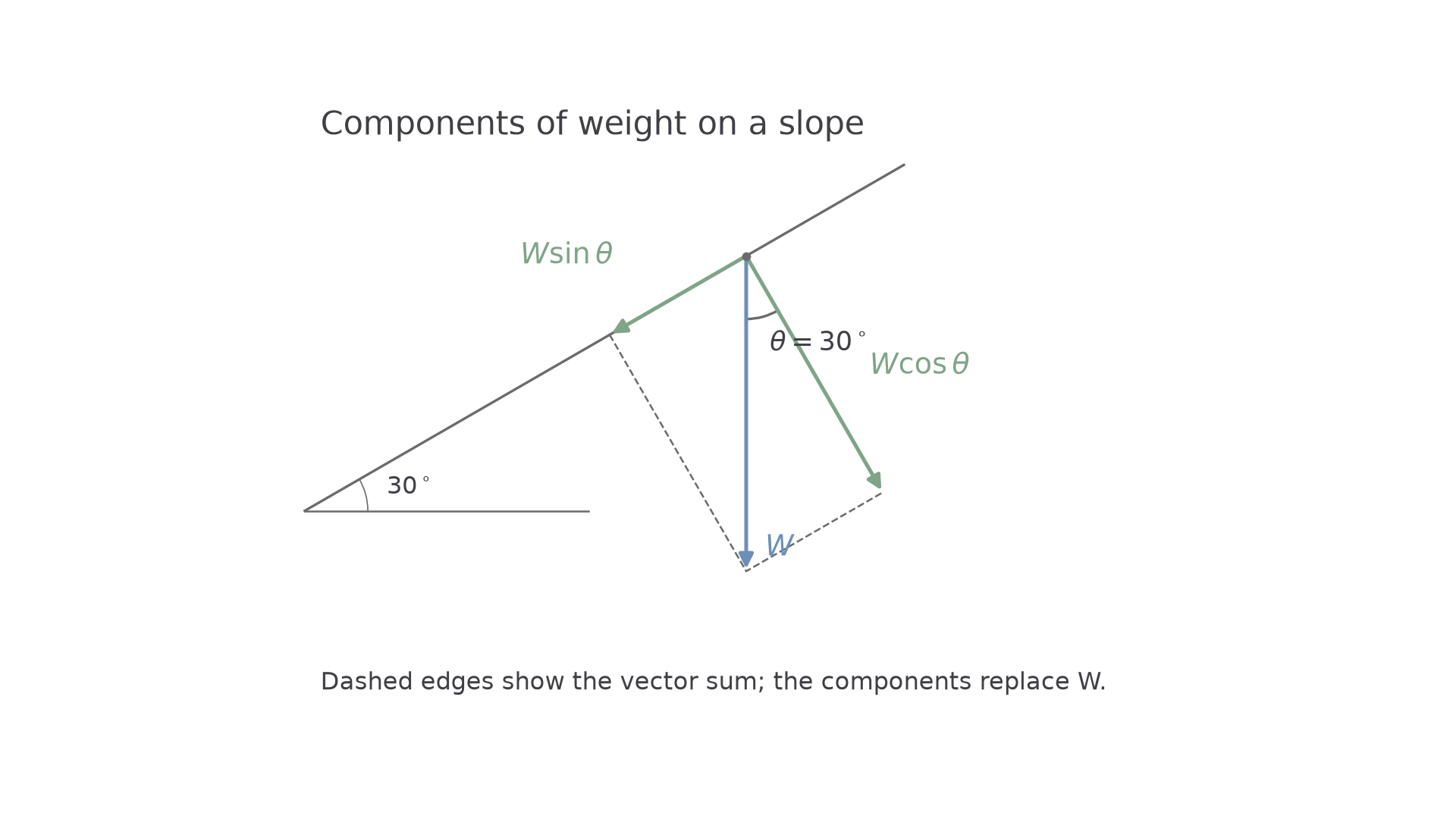
For a weight on a slope, the components are down the plane and into it. Check the limiting case: on a horizontal plane the parallel component is zero.
Equilibrium and a force-board test
A point object is in equilibrium when its resultant force is zero. It can be at rest or moving at constant velocity. For forces in one plane,
Two forces balance when equal and opposite. Three forces balance when their arrows, drawn to scale tip-to-tail, make a closed triangle. These conditions concern forces acting at a point; an extended body also needs zero resultant moment.
[DIAGRAM: asset_name: 4.1.1 - Scalars and Vectors - Diagram 5; asset_slug: 4.1.1 - Scalars and Vectors - Diagram 5; recommended_method: retained_png; caption: All three arrows go consecutively around the closed triangle, giving zero resultant.; description: All three arrows go consecutively around the closed triangle, giving zero resultant.]
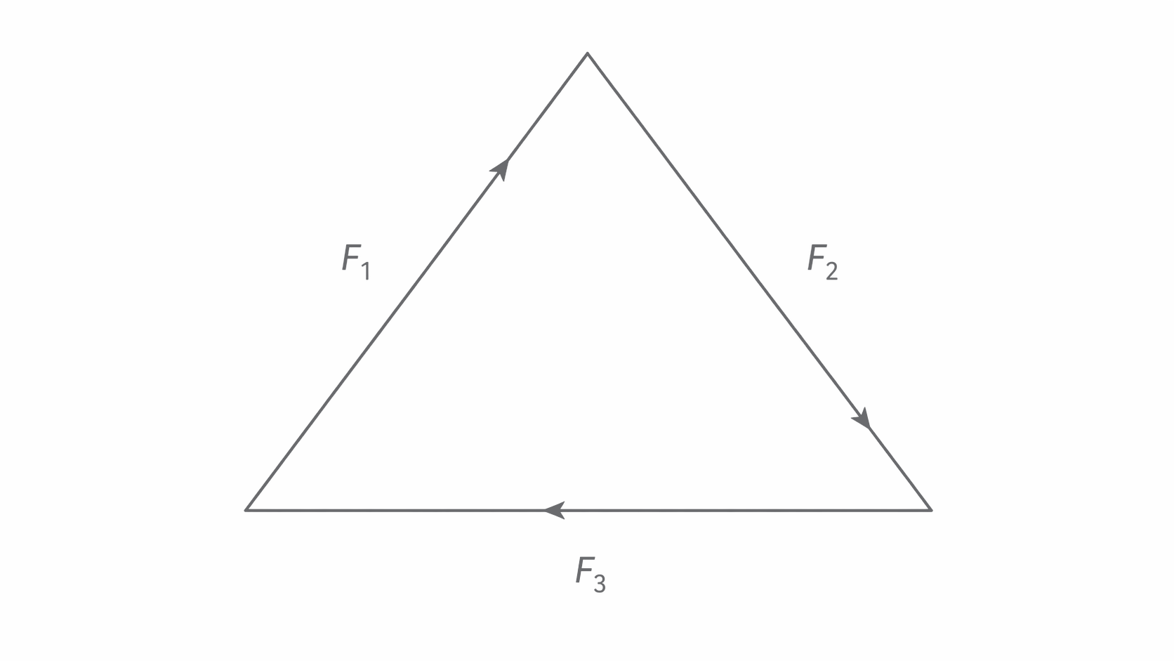
Draw a free-body diagram by isolating one object and adding only the forces acting on it. For a block at rest on a rough slope with no other applied force, include weight vertically down, normal reaction perpendicular out of the plane, and friction up the plane. Resolving gives and . These equalities depend on the stated equilibrium and force arrangement; friction does not always equal .
For a point with downward and right, the balancing third force has components up and left: at above the horizontal to the left. The equilibrant is opposite to the resultant, not along it.
Test with three coplanar forces
On a vertical force board, pass two strings over low-friction pulleys to hanging masses and attach a third hanging mass directly to the common knot. Include the mass hangers when calculating each tension . Let the knot settle, record the three string directions on paper behind it, and draw a force triangle to scale. Closure within measurement uncertainty supports equilibrium. Alternatively resolve all three tensions and compare each residual sum with the uncertainty. Check that masses hang freely, strings lie in the board's plane, and pulleys turn freely. Reposition the knot and repeat to reveal pulley friction or angle-reading scatter. A fixed viewing position normal to the board reduces parallax.