3.13.6.2 - Transmission Media
Choose a transmission medium by explaining how it carries information and weighing capacity, range, installation cost and interception risk. Radio propagation and satellite relay make communication possible where a direct cable or line of sight is unavailable.
Electrical signals in metal cables
Metal cables carry electrical signals between connected devices. Copper cable can be economical for a short local connection, especially when it is already installed, but losses and interference restrict useful distance and data rate.
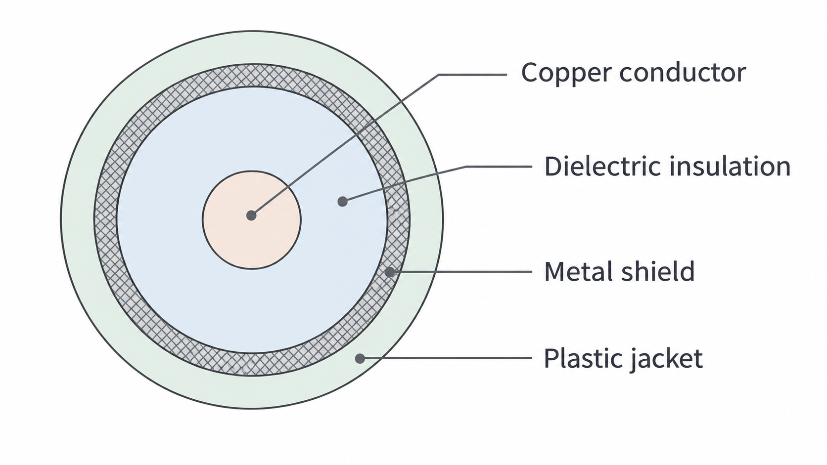
A coaxial cable has a central conductor, dielectric insulation and an enclosing conducting shield, all protected by an outer jacket. The shield reduces external electromagnetic interference; the plastic insulation does not provide this electrical shielding.
[DIAGRAM: asset_name: E.6.2 - Transmission Media - Diagram 1; asset_slug: E.6.2 - Transmission Media - Diagram 1; caption: The conductor, dielectric, shield and jacket of a coaxial cable; description: The conductor, dielectric, shield and jacket of a coaxial cable]
A twisted pair uses two insulated conductors with a receiver that responds to their voltage difference. Twisting makes the conductors experience similar interference. Noise added approximately equally to both is rejected when the receiver takes the difference: it is not necessary for the unwanted voltages to be opposite in sign. For example, adding to each wire leaves a wanted difference unchanged.
Unshielded, untwisted connections are more vulnerable to interference. The detailed performance of a cable depends on its construction, length and equipment; “all copper is slow” is not a useful comparison. Typical short electrical links have less available bandwidth than a high-capacity optical-fibre link. A cable may be tapped if an intruder gains access, so a physical connection does not guarantee confidentiality.
Confining light and preserving pulses
An optical fibre guides light through a transparent core surrounded by lower-refractive-index cladding. In the ray model, light travelling in the higher-index core undergoes total internal reflection when its incidence angle, measured to the normal, exceeds the critical angle.
[DIAGRAM: asset_name: E.6.2 - Transmission Media - Diagram 2; asset_slug: E.6.2 - Transmission Media - Diagram 2; caption: Total internal reflection at a core–cladding boundary; description: Total internal reflection at a core–cladding boundary]
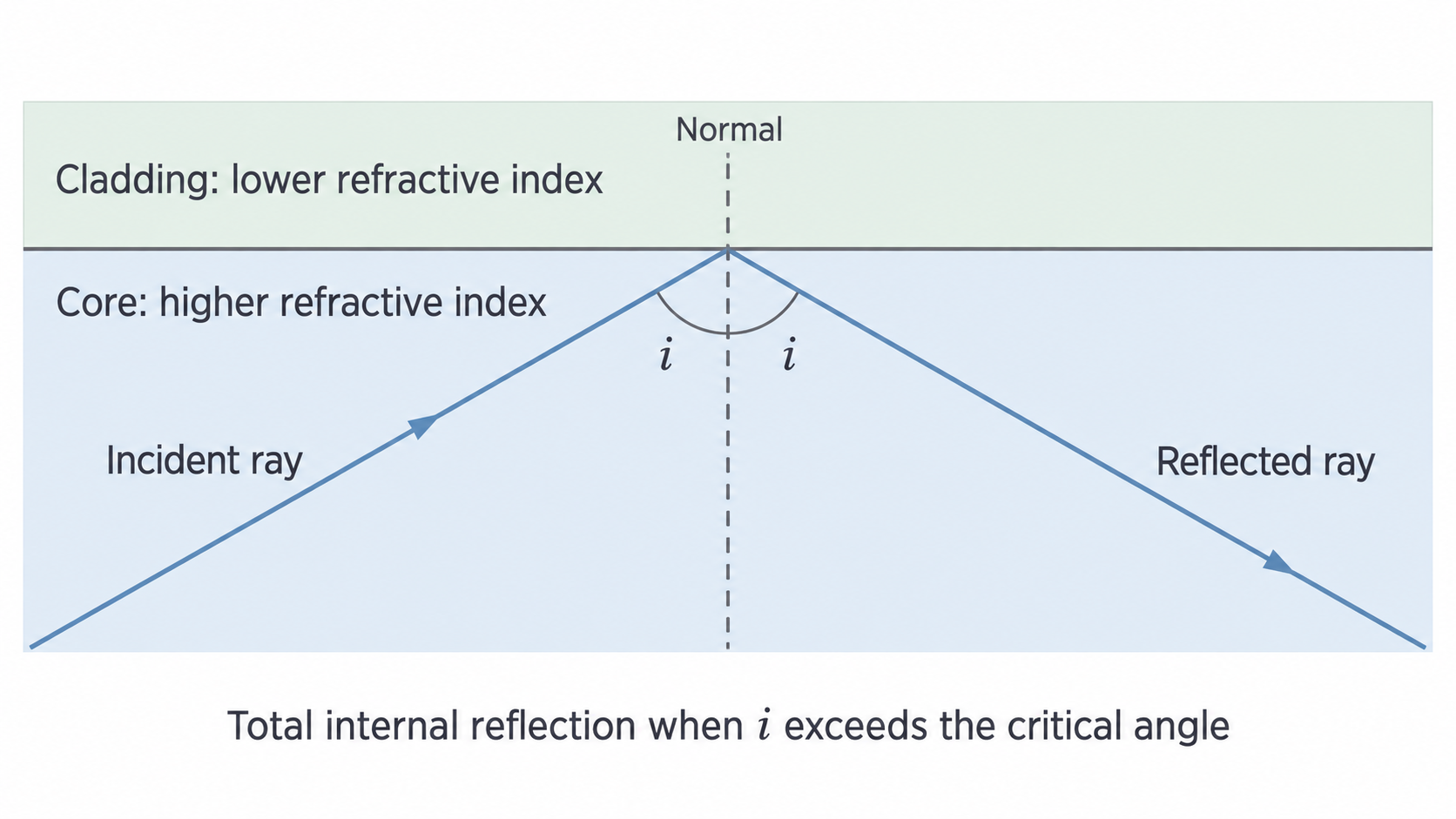
The critical angle satisfies . For indices and , respectively, . A ray at to the normal is totally internally reflected. At the critical angle itself the refracted ray would travel along the boundary.
Fibre has low attenuation and very large available bandwidth. It does not pick up electrical interference from nearby power cables. However, attenuation reduces received optical power, and dispersion spreads a pulse in time. If neighbouring pulses overlap, distinguishing them becomes difficult, limiting the data rate over that distance.
In multimode fibre, different modes have different travel times; this produces modal dispersion. Single-mode fibre removes this particular source of spreading, although other dispersion and attenuation remain. Long links may need optical amplification or regeneration. Fibre requires suitable transmitters, detectors and careful joints, and laying a new route can be expensive.
Fibre is usually harder to intercept than a radiated radio link because access to the cable is needed and little light escapes normally. It is not impossible to tap and need not be broken to intercept it; confidential data still require protection.
Ground waves, sky waves and line of sight
Radio waves can reach a receiver by different routes, and wavelength helps determine which routes are effective. The following ranges are typical communication examples, not sharp universal boundaries.
| Example | Approximate frequency | Wavelength in free space |
|---|---|---|
| Longwave | – | – |
| Shortwave | – | – |
| Microwave communication | – | – |
These pairs follow . For example, , so a link has wavelength .
[DIAGRAM: asset_name: E.6.2 - Transmission Media - Diagram 3; asset_slug: E.6.2 - Transmission Media - Diagram 3; caption: Three radio propagation paths shown schematically; description: Three radio propagation paths shown schematically]
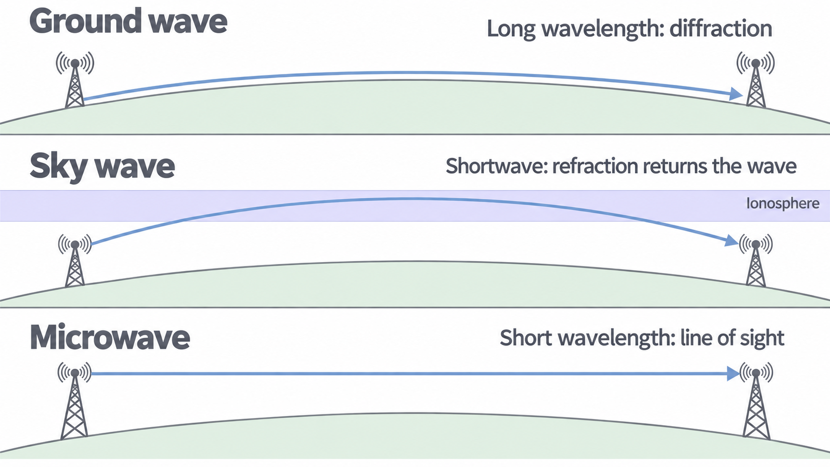
Ground waves follow the Earth's surface. Long wavelengths diffract more strongly around obstacles and the curved surface than short wavelengths do, allowing reception beyond simple line of sight. This does not mean a kilometre wavelength is comparable with the Earth's radius. Ground-wave signals still attenuate, and some locations can remain in a shadow. The available bandwidth is limited.
Continue this lesson.
You’re previewing NovaLearn without an account. Create a free account to read the rest.
Create free account