3.5.1.4 - Circuits
Use charge and energy conservation to recognise series and parallel connections, simplify resistor networks and check their currents, pds and powers. The connections between nodes determine the physics, not the way a circuit is drawn.
Series paths and parallel nodes
Components are in series when the same current must pass through each, with no conducting branch between them. Components or whole branches are in parallel when they connect between the same two nodes. A node includes every point joined by ideal wire: the pd along such a wire is zero.
For a steady circuit, charge does not build up at a junction or get used up in a resistor. The current is therefore the same along a series path, and currents entering a junction add to those leaving it. Parallel branches need not have equal currents.
[DIAGRAM: asset_name: 5.1.4 - Circuits - Diagram 1; asset_slug: 5.1.4 - Circuits - Diagram 1; caption: A 12 V ideal source supplies three series resistors. Ideal voltmeters draw no current, and the three resistor pds sum to 12 V.; description: A 12 V ideal source supplies three series resistors. Ideal voltmeters draw no current, and the three resistor pds sum to 12 V.]
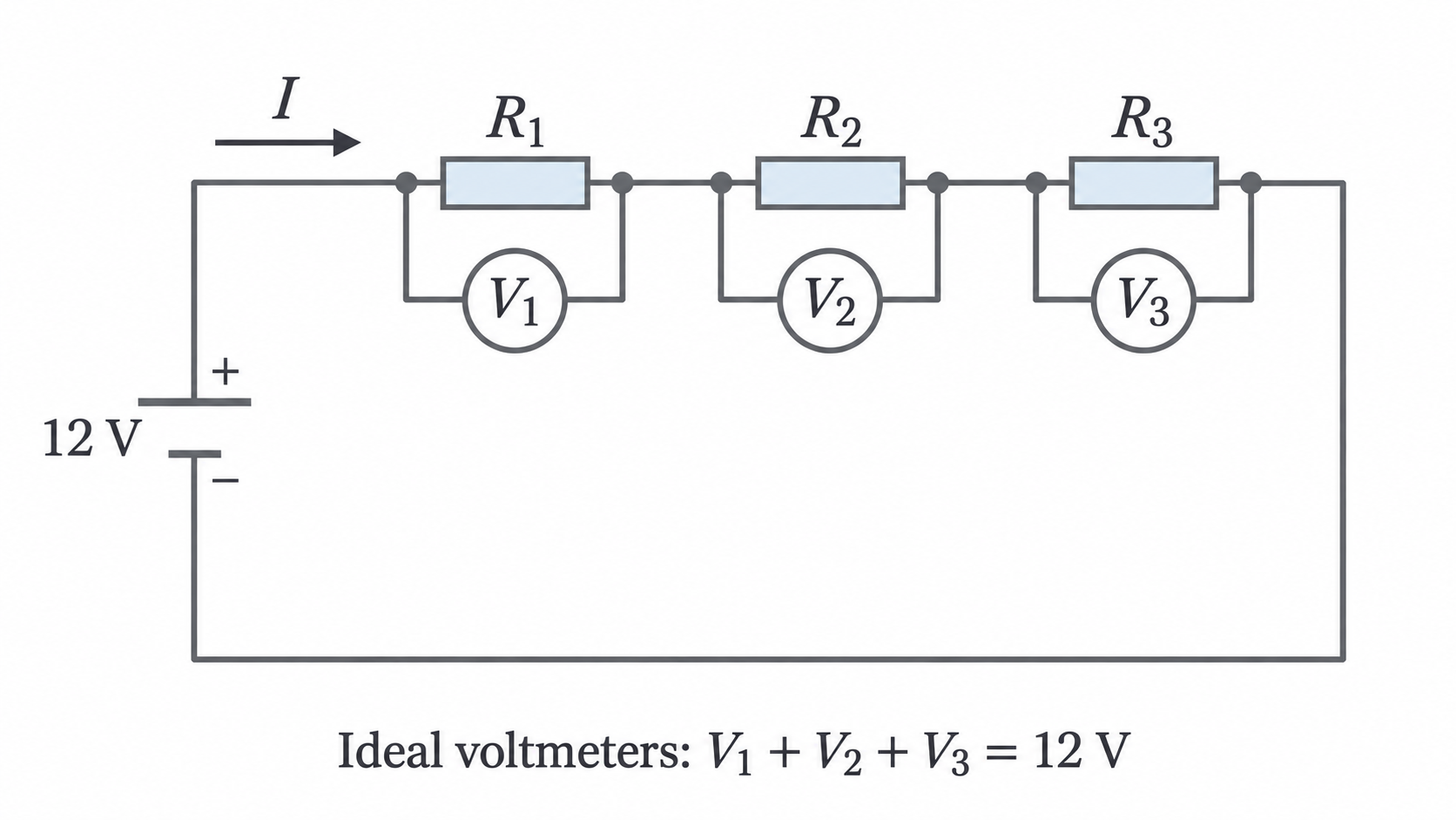
Energy transferred per coulomb around a complete loop balances the energy supplied per coulomb. Thus series pds add to the total pd across the combination. Parallel branches have the same pd because they share the same pair of endpoints.
[DIAGRAM: asset_name: 5.1.4 - Circuits - Diagram 2; asset_slug: 5.1.4 - Circuits - Diagram 2; caption: The parallel branches share the same two nodes. With ideal ammeters their drops are zero, so each voltmeter reads its resistor pd. Ideal voltmeters draw no current.; description: The parallel branches share the same two nodes. With ideal ammeters their drops are zero, so each voltmeter reads its resistor pd. Ideal voltmeters draw no current.]
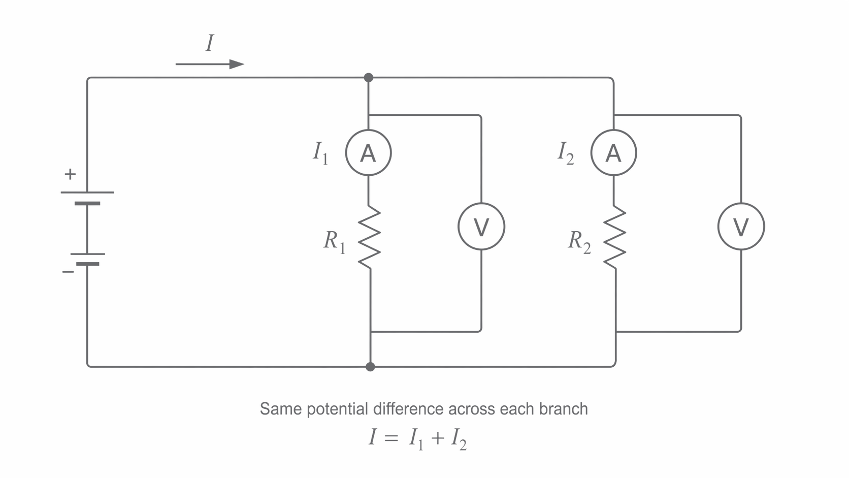
To test these rules in a low-voltage circuit, measure current before and after a resistor by placing an ammeter in series at each position. Compare the branch-current sum with the supply current. Measure each component pd with a parallel voltmeter and compare its sum with the measured terminal pd. Agreement is limited by meter uncertainty; it is not evidence that current is consumed.
Conservation around a complete loop
Kirchhoff’s junction law expresses conservation of charge: total current entering equals total current leaving a junction in a steady circuit. Kirchhoff’s loop law expresses conservation of energy: the algebraic sum of potential changes around any closed loop is zero.
Choose a direction around a loop and keep the signs consistent. Traversing a cell from negative to positive gives an emf rise. Traversing a resistor in the conventional-current direction gives a pd drop. For a source supplying two resistors, this gives . If one cell opposes another, its emf must be subtracted, not added blindly.
For instance, opposing ideal cells of and driving give , so . A negative solution means the actual current is opposite to the assumed direction; it is not a negative resistance.
The simple statement “sum of emfs equals sum of resistor drops” assumes a consistent traversal and signs. In a network, choose each loop explicitly: do not add the pds of two parallel branches as if a single charge had passed through both.
Equivalent resistance follows from the circuit rules
Series resistors carry the same current. Since , substituting gives , hence
For positive resistors the total exceeds any individual resistance.
Parallel resistors share the same pd. Since , substitution gives , hence
For two resistors this gives . The total is smaller than either positive branch resistance: at a fixed pd the added branch carries additional current. Two resistors in parallel give , not .
Reducing a mixed network
A resistor in series with a parallel pair of and gives , then . With an ideal supply the total current is , but that is not the current through each parallel resistor. Their shared pd is , so their currents are and , summing to .
Cells in series and identical cells in parallel
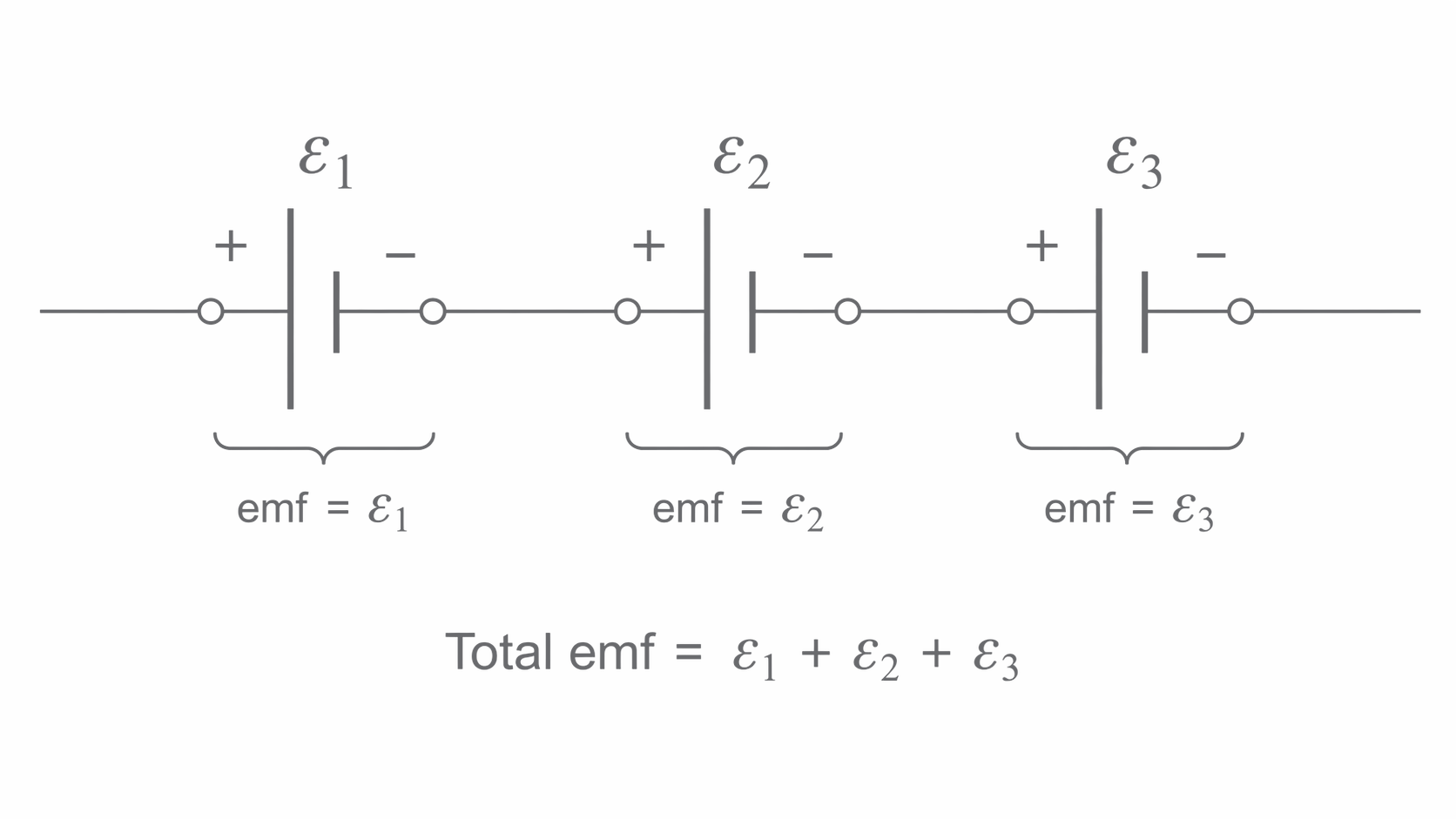
Cells connected in series with aiding polarities add their emfs because a charge receives energy from every cell in turn. An opposing cell subtracts from that signed total.
[DIAGRAM: asset_name: 5.1.4 - Circuits - Diagram 3; asset_slug: 5.1.4 - Circuits - Diagram 3; caption: Three cells in series with aiding polarities: their emfs add. Opposing a cell reverses its contribution to the total.; description: Three cells in series with aiding polarities: their emfs add. Opposing a cell reverses its contribution to the total.]
Identical cells in parallel connect positive terminals together and negative terminals together. Each parallel cell spans the same terminal pd. The pack emf is one cell’s emf, not their sum. Each cell supplies a share of the total current; for identical cells and connections the shares are equal. More cells can therefore supply the load for longer or reduce the load on each cell.
For real identical cells, each with internal resistance , the parallel equivalent is ; in series it is . The emf is in parallel and in aiding series. Internal resistance is developed in lesson 3.5.1.6. If internal resistance is neglected entirely, parallel cells do not increase current through an unchanged resistor: the applied pd stays the same.
For three identical ideal cells and a load, an aiding series pack supplies . A parallel pack supplies in total. Do not extend the identical-cell rule to mismatched cells.
Power depends on what stays constant
Electrical energy transferred by a component is . With steady current , so . Power is energy transferred per second:
Use current through and pd across the same component. Power is measured in watts and energy in joules; requires seconds when power is in watts.
Which resistor dissipates more power depends on the connection. In series, the same current passes through both, so : a larger resistance dissipates more power. In parallel, the same pd spans both, so : a smaller resistance dissipates more power. “Larger resistance means greater power” is incomplete without the condition held fixed.
For a , lamp operating at its rating, . In , it transfers . Its operating resistance is ; its cold resistance can differ.
A resistor’s power rating is the maximum intended dissipation under stated conditions. Compare the calculated component power with that rating before choosing the resistor; an acceptable voltage alone does not establish safe operation.
Recovering branch values and checking energy
Replacing a network by one equivalent resistor gives the supply current, but it hides the branch values. Recover them by working from the whole circuit back to each branch, keeping the junction and loop conditions intact.
Consider and in series as one branch, in parallel with , all across an ideal source. The branches are and , so the equivalent is and total current is .
The series branch takes , passing through both its resistors. The separate branch takes . The series pds are and , adding to . Resistor powers are , and , totaling , which equals source power .
These checks reveal different mistakes: an incorrect branch-current sum violates charge conservation; a wrong loop-pd sum violates energy conservation per charge; a wrong power sum violates total energy transfer per second. A correct total resistance does not guarantee correct branch calculations.