3.10.5.1 - The Physics of Diagnostic X-rays
An X-ray tube converts the energy of accelerated electrons into radiation and heat. Learn how its spectrum is produced, then connect the tube controls and imaging geometry to sharpness, contrast and absorbed dose.
Production of X-rays
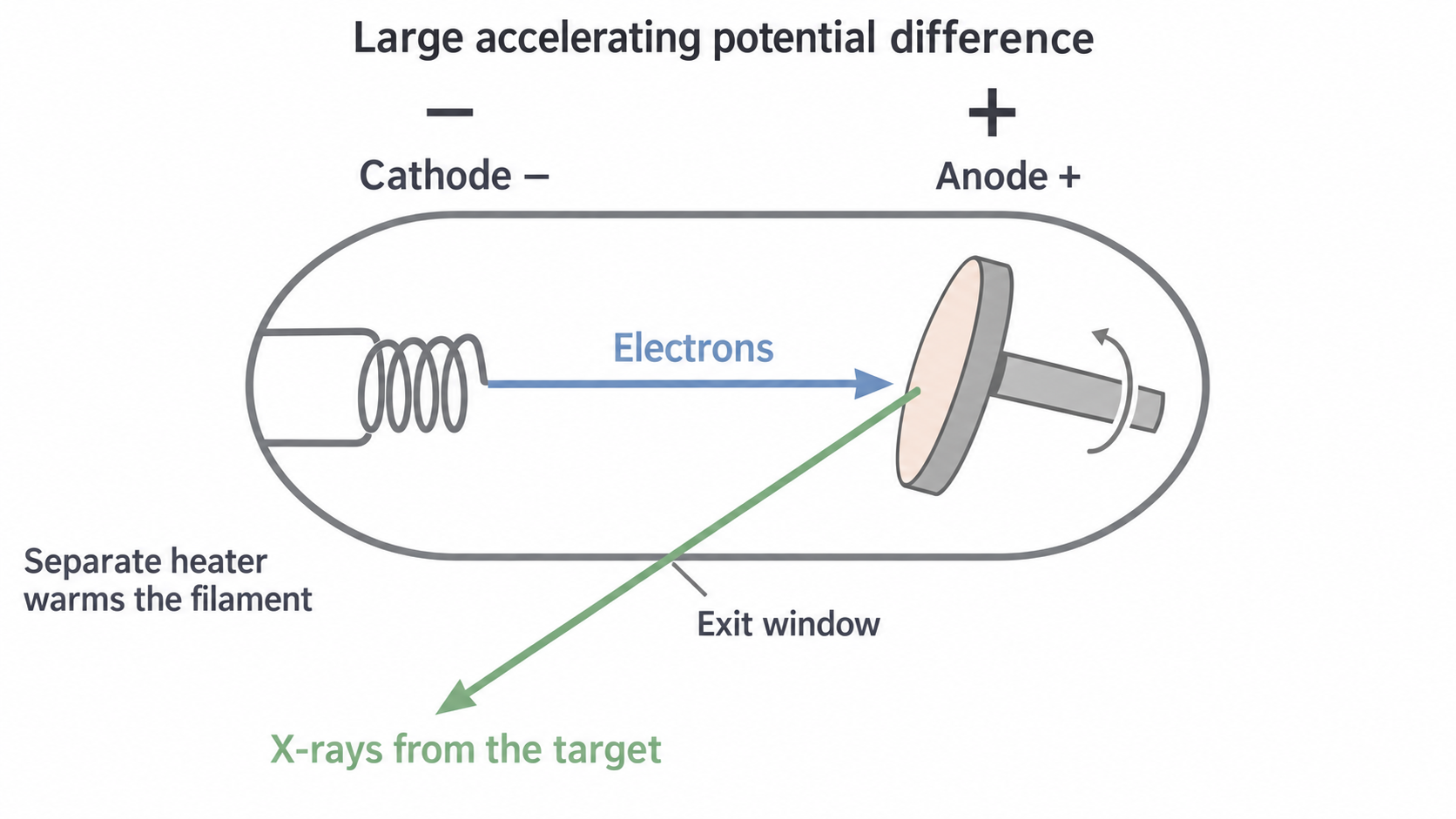
A heated metal cathode releases electrons by thermionic emission: heating supplies energy for electrons to escape the surface. A separate high-voltage supply makes the anode positive relative to the cathode, accelerating the negative electrons towards a metal target. The tube is evacuated so electrons can reach the target without substantial collisions with gas molecules. X-rays originate at the target, not at the filament.
[DIAGRAM: asset_name: B.5.1 - The Physics of Diagnostic X-rays - Diagram 1; asset_slug: B.5.1 - The Physics of Diagnostic X-rays - Diagram 1; caption: Electrons accelerate from the negative cathode to the positive rotating target; description: Electrons accelerate from the negative cathode to the positive rotating target.]
A continuous spectrum with an energy limit
An electron passing near a target nucleus is deflected and decelerated by its electric field. Some of its kinetic energy is emitted as a photon: bremsstrahlung, or braking radiation. Different encounters transfer different amounts of energy, so the emitted photons form a continuous range of energies. Most electrons also transfer energy in interactions that heat the target.
Neglecting the electron's initial kinetic energy, the work done by the accelerating field is . A photon cannot receive more than this from one incident electron. If an electron transfers all its kinetic energy to one photon,
For example, at , . Using , and gives . This is a limiting photon energy, not the energy of every photon.
Characteristic lines
An incident electron can eject an inner-shell electron from a target atom if it has enough energy. An electron in a higher level then fills the vacancy, emitting a photon of energy . Only particular level differences exist, so sharp characteristic lines appear on the continuous background. Their energies depend on the target element. Raising the tube voltage does not slide existing characteristic lines to new energies, although it can make previously inaccessible transitions possible.
[DIAGRAM: asset_name: B.5.1 - The Physics of Diagnostic X-rays - Diagram 2; asset_slug: B.5.1 - The Physics of Diagnostic X-rays - Diagram 2; caption: An illustrative X-ray energy spectrum has characteristic lines and a voltage-set endpoint; description: An illustrative X-ray energy spectrum has characteristic lines and a voltage-set endpoint.]
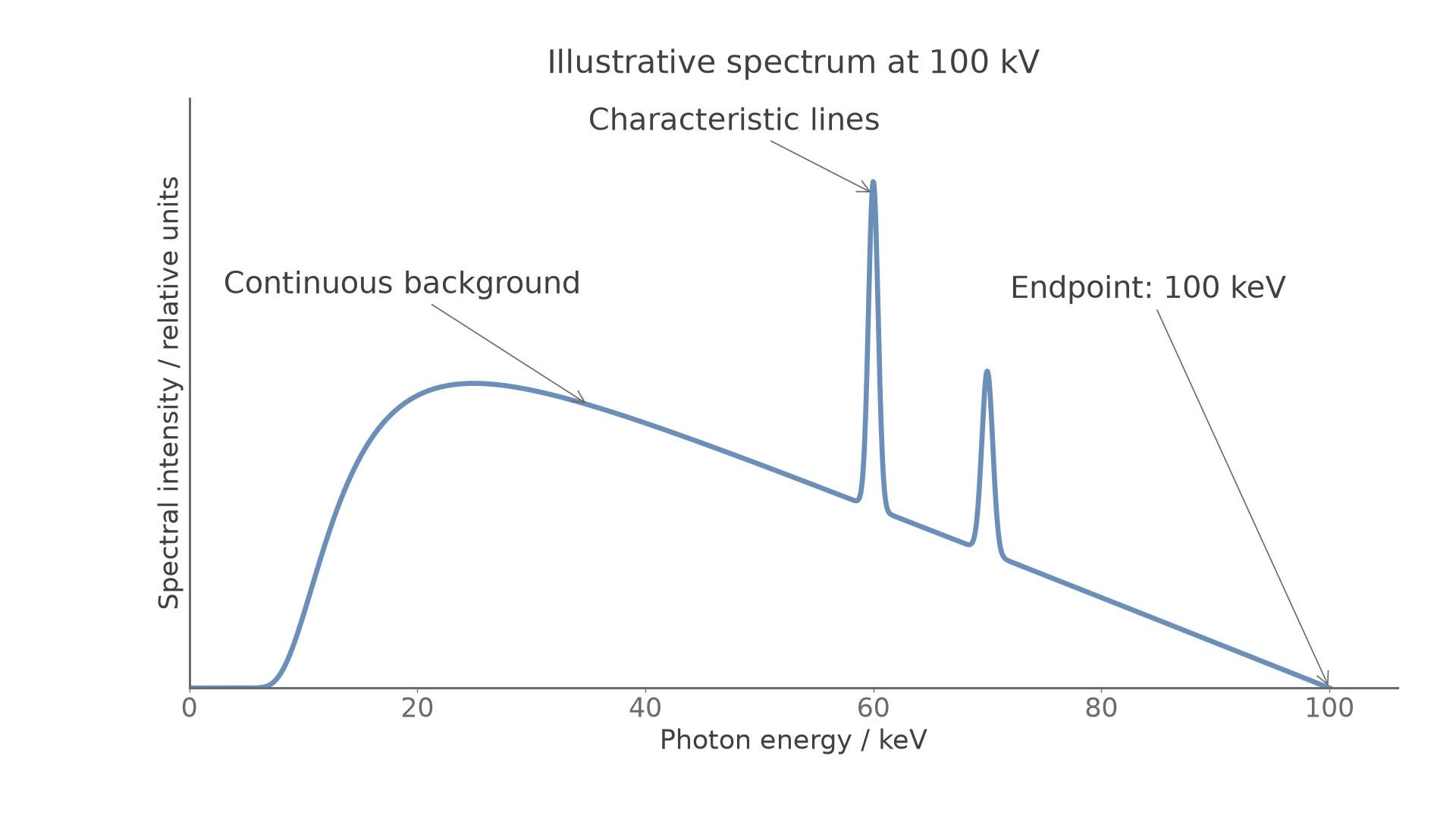
The vertical axis is spectral intensity per photon-energy interval in relative units. Its height is not photon energy: read photon energy along the horizontal axis. The low-energy shape includes absorption within the target and tube. The plotted line positions illustrate a target rather than prescribing values to memorise.
The rotating-anode X-ray tube
Most of the incident electron energy heats the target; only a small fraction becomes X-rays. The fraction depends on operating conditions, so use the efficiency supplied in a calculation rather than treating as a universal constant.
Tungsten combines a high melting point with high atomic number. It withstands a high temperature, and its large nuclear charge makes bremsstrahlung production effective. These properties do not remove the heat: energy must still be transferred from the anode to its surroundings.
Rotation sweeps the electron impact across a track on the target. Each small patch is bombarded for only part of a revolution, reducing the local temperature rise compared with continuously hitting one fixed patch. The heat is distributed over more material; it has not disappeared because the target rotates.
The focal-spot compromise
A small X-ray source makes a sharper shadow, but concentrating the same electron power onto too small an area risks overheating. An angled target provides a relatively large actual focal area struck by electrons and a smaller effective focal spot as viewed towards the detector. This is the line-focus principle.
[DIAGRAM: asset_name: B.5.1 - The Physics of Diagnostic X-rays - Diagram 3; asset_slug: B.5.1 - The Physics of Diagnostic X-rays - Diagram 3; caption: The actual target spot projects to a smaller effective source size; description: The actual target spot projects to a smaller effective source size.]
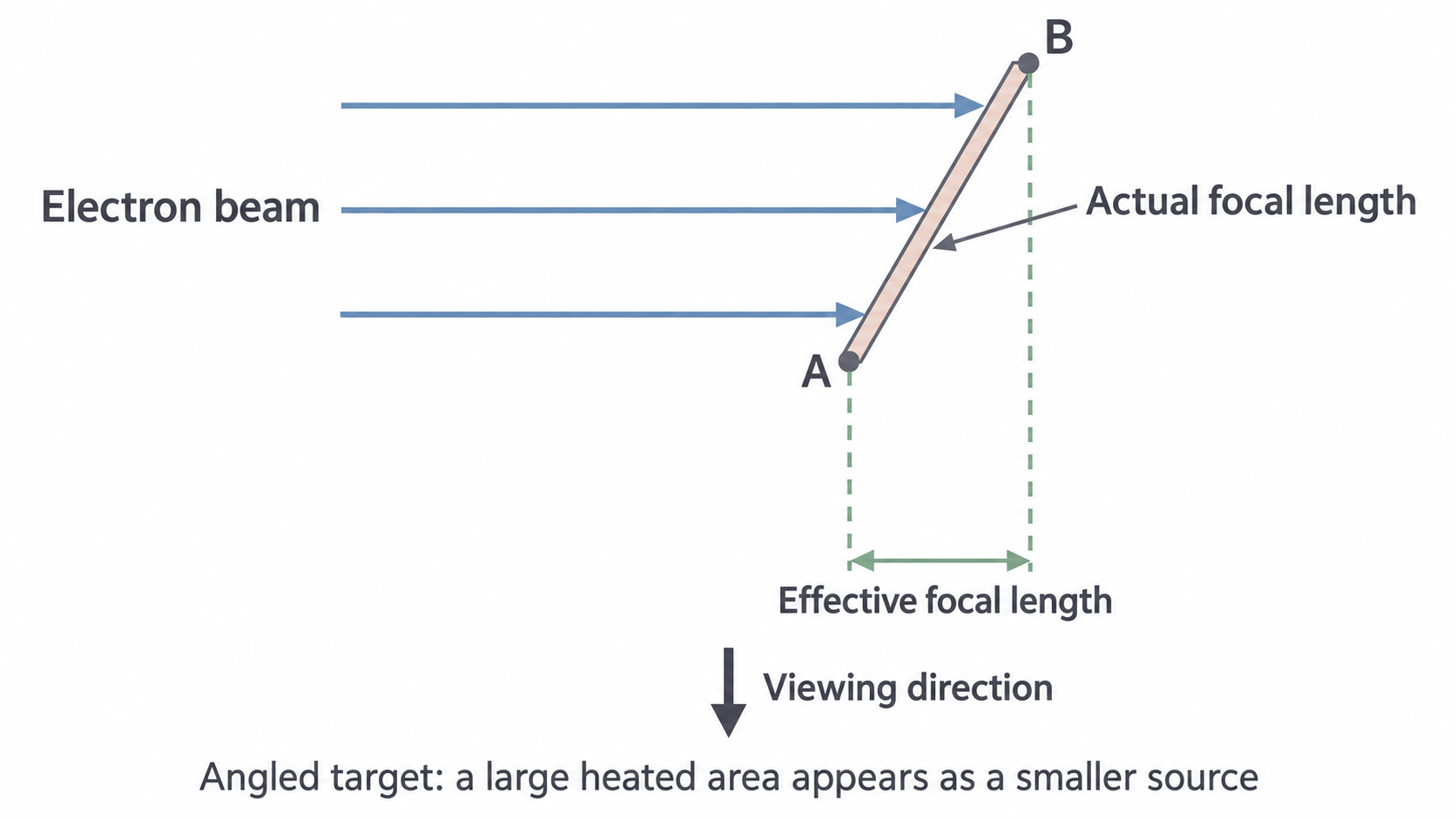
Here “focal length” labels the length of the focal spot along the illustrated direction, not the focal length of a lens. The two dashed guides start at opposite ends of the heated region and project its apparent width. Rotation distributes heat over the track while this angled geometry reduces the apparent source size.
For a tube at with tube current , the electron-beam power is . If becomes X-rays, about initially heats the target. A high melting point, rotation and heat removal are therefore all useful, even for brief exposures.
Controlling beam intensity and photon energy
Beam intensity is energy crossing unit area perpendicular to the beam per second, measured in . It depends on how many photons arrive and on their energies. It is different from the energy of one photon.
The filament current heats the cathode. Increasing it increases thermionic emission under normal operating conditions. The resulting tube current, , is the rate of charge flow across the vacuum from cathode to anode. These are different currents in different circuits. The number of electrons reaching the target per second is .
Continue this lesson.
You’re previewing NovaLearn without an account. Create a free account to read the rest.
Create free account