D2 3.4, 3.5 - Multiple sources, sinks and restricted capacities
You will combine several sources and sinks, represent a restricted vertex, and find feasible flow patterns with upper and lower arc capacities.
Combine sources and sinks without changing the real network
Can increasing a pipe's minimum required flow reduce the maximum delivered by the whole network, even when every upper capacity stays fixed? It can: a compulsory flow back across a cut reduces its net outward capacity. We will reach a concrete example after learning how to represent the different restrictions.
You already know
The labelling procedure starts from a feasible directed flow and uses forward and reverse residual arrows. Conservation holds at intermediate nodes. A feasible pattern and a matching valid cut bound prove that an optimum is attained.
Several suppliers or receiving stations do not need a different flow algorithm. Add an artificial source and sink so that the real network sits inside a single-source, single-sink model.
Supersource and supersink
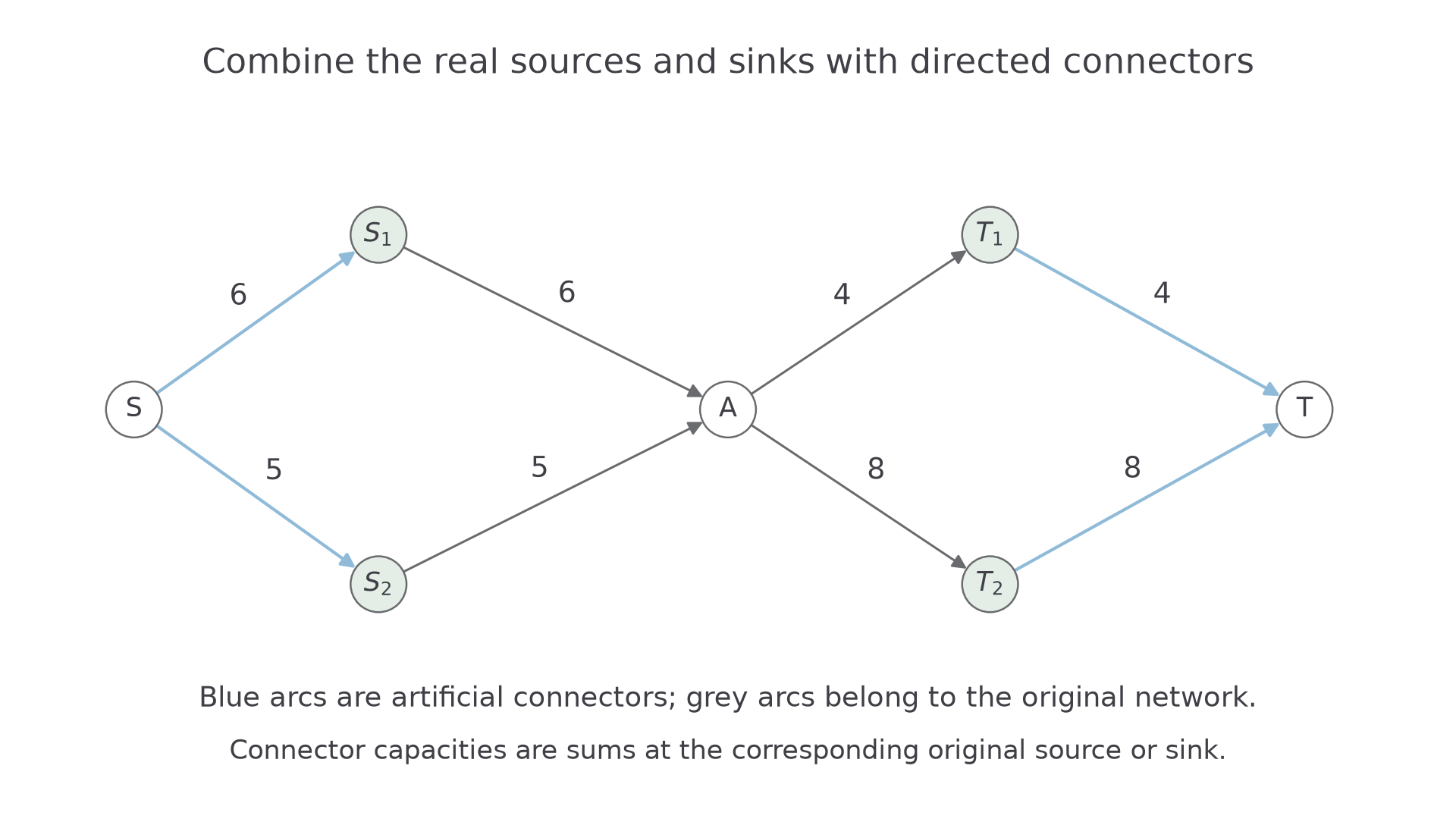
Join a supersource S to every original source . Give capacity equal to the sum of capacities leaving .
Join every original sink to a supersink T. Give capacity equal to the sum of capacities entering .
The added arrows point into the original sources and out of the original sinks. They aggregate the total flow without imposing an extra bottleneck.
These connector capacities are the ordinary construction when no smaller external supply or receiving limit is stated. Any additional stated limit must still be respected.
Not in the formula booklet: learn it.
[DIAGRAM: asset_name: Adding a supersource and supersink; asset_slug: 9fm0-d2-187-super-nodes; caption: New connectors aggregate the two original sources and two original sinks.; description: Directed network S to S1 capacity6 and S2 capacity5, S1 to A capacity6 and S2 to A capacity5, A to T1 capacity4 and T2 capacity8, then T1 to T capacity4 and T2 to T capacity8; original arcs grey, artificial connectors blue and original source/sink nodes sage.]
Worked example 1: two supplies and two destinations
Question. A network has arcs of capacity , of capacity , of capacity , and of capacity . Add a supersource and supersink, then determine the maximum total flow.
Plan. Give the artificial connectors their aggregate capacities, exhibit a feasible pattern and match it to a cut.
Add
The source-side cut has capacity ; the sink-side cut has capacity .
Use real-arc flows
Give the corresponding artificial connectors the same flows.
Why is , rather than , sent to ? A receives only , and of it goes to . Capacities are available room, not compulsory amounts.
Answer. Maximum flow is , attained by the displayed pattern and bounded by the cut through the two source connectors.
Check. A has inflow and outflow ; every real and artificial arc respects its capacity.
Worked example 2 changes only the original capacity , from to .
Worked example 2: recalculate the affected connector
Question. Find the new supersource connector capacity and maximum total flow.
Plan. Update the aggregate capacity leaving , then produce a matching feasible pattern.
The connector now has capacity . The others remain . Thus the source cut has capacity .
Use
with the same corresponding connector flows.
Why change the artificial connector too? It is defined by the original source's outgoing capacity, not an independent extra supply.
Answer. The new maximum is .
Check. A receives and sends , the sink capacities allow this split, and the source cut prevents any larger total.
After finding a flow in the augmented network, report what each real source supplies and each real sink receives. The supersource and supersink are modelling devices.
Watch out
Wrong: point a connector towards the supersource, add capacities of unrelated arcs, or assume every connector must be full. Right: use the prescribed directions and sums, then find a feasible overall pattern.
Increase the same original source capacity instead.
Put a vertex limit on an internal arc
An arc capacity limits one connection. A vertex restriction limits all flow passing through a junction, even when several incoming and outgoing arcs could individually carry much more.
Splitting a restricted vertex
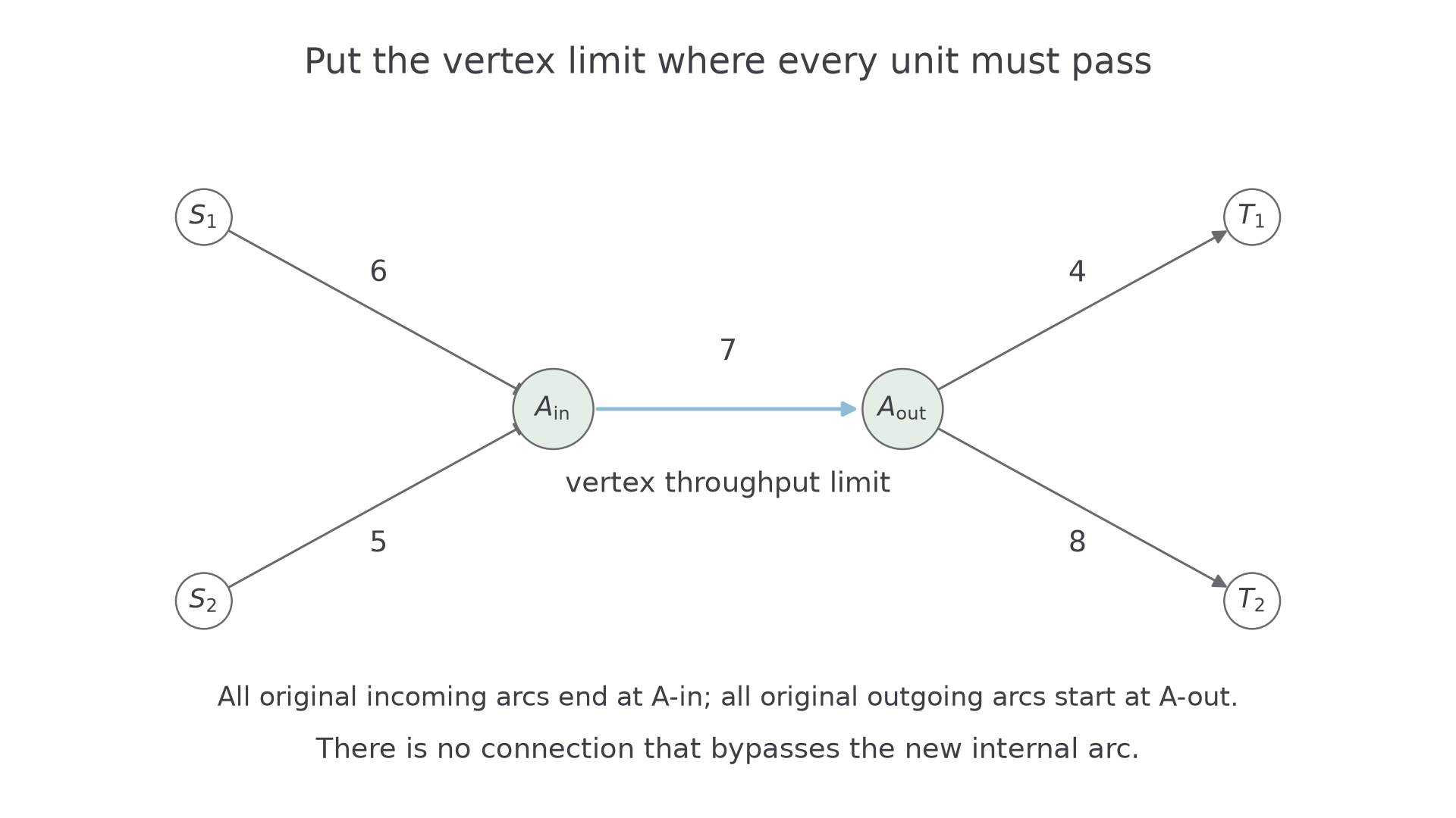
Replace a vertex A by two vertices and .
- Direct every original incoming arc into .
- Direct every original outgoing arc out of .
- Join with capacity equal to A's permitted throughput.
Keep every original arc's capacity and direction. Every unit passing through A must now use the new internal arc.
This converts a vertex restriction into an ordinary arc restriction, so the same labelling and cut ideas apply.
Not in the formula booklet: learn it.
[DIAGRAM: asset_name: Splitting a restricted junction; asset_slug: 9fm0-d2-187-split-vertex; caption: All incoming flow reaches A-in, crosses the7-capacity internal arc, then leaves A-out.; description: S1 and S2 send through capacities6 and5 to A-in, a blue directed internal arc of capacity7 joins A-in to A-out, and A-out sends through capacities4 and8 to T1 and T2; split nodes sage, no bypass arc.]
Worked example 3: a junction becomes the bottleneck
Question. Return to the original network with incoming capacities and outgoing capacities . A can now pass at most units per second. Represent the restriction and find the maximum total flow.
Plan. Split A, insert a -capacity internal arc, and attain its cut bound.
The internal arc is , capacity . Use real-arc flows into , then out of . The internal flow is .
The cut with
and all remaining nodes in Y crosses only the internal arc, so its capacity is .
Why must every incoming arc end at ? An incoming connection to would bypass the restriction.
Answer. The split representation gives maximum flow .
Check. The source supplies , the internal arc carries , and the destinations receive .
Worked example 4 changes only A's throughput limit, from to .
Worked example 4: relax the vertex restriction
Question. Find the maximum total flow with the new vertex limit .
Plan. Change only the capacity of the internal split arc and construct a new feasible split.
Set . Send from the original sources, pass along the internal arc, and send to the original sinks.
Why keep the other capacities fixed? The restriction belongs to the vertex. It does not alter any individual real pipe.
Answer. Maximum flow is , matching the internal cut capacity .
Check. Both source flows fit within , both destination flows within , and conservation holds at the two split nodes.
A large vertex limit need not be the active bottleneck. Compare it with all other relevant cuts, and still give an achieving pattern.
Watch out
Wrong: reduce every incoming capacity to the vertex limit, or leave an arc that bypasses the internal link. Right: preserve the original arcs and put the total-throughput limit on the single directed split arc.
Make the same vertex limit larger than total available source capacity.
Respect lower capacities before augmenting
A lower capacity is a requirement, not spare room. With a positive lower bound, zero flow may be infeasible, and potential backflow cannot undo the compulsory part.
Continue this lesson.
You’re previewing NovaLearn without an account. Create a free account to read the rest.
Create free account