E7.1 - Negative enlargements and combined transformations
Changing a centre, the sign of a scale factor or the order of two movements can change an image completely. You will extend reflection to sloping lines, rotate about any centre, draw negative enlargements and carry out transformations in order. These are Extended applications of E7.1.
Reflections in sloping lines
Does reflecting a point and then translating it give the same result as translating first? Keep that question for the last part. First extend the reflection rule: the mirror can slope, but it must still bisect every point–image segment at right angles.
For any straight mirror line, draw a perpendicular from a vertex to the line. Continue it the same distance on the opposite side. Repeat for every vertex, then rule the image sides in the original vertex order. A ruler and set square help you draw accurate perpendiculars. The image is not generally horizontally or vertically opposite the original.
Reflection in a sloping line
For a point off the mirror, the mirror line is the perpendicular bisector of the segment joining the point to its reflected image. Points on the mirror remain fixed. The rule applies to any straight line, including , and lines with other gradients or intercepts.
For , horizontal and vertical distances exchange roles: maps to . For , the image is . These shortcuts apply to those particular lines, not to every sloping mirror.
[DIAGRAM: asset_name: Reflecting in sloping mirrors; asset_slug: sloping_reflections; caption: The joining segment is perpendicular to the mirror and bisected by it.; description: Two equal-scale coordinate grids show triangle A at one three B at three four C at one five. Left reflection is in y equals x with image three one four three five one. Right reflection is in y equals one half x with images three negative one five zero and four point six negative two point two. Perpendicular joining segments and mirror feet are shown, with the A pair emphasised.]
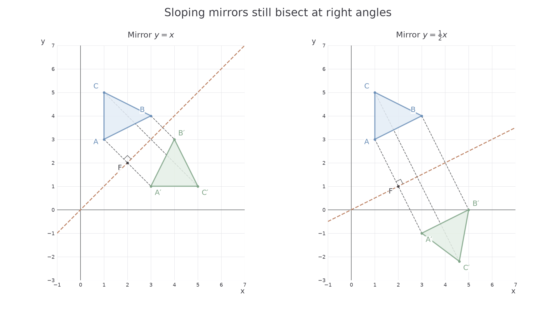
Worked example 1: reflection in the diagonal
Question. Reflect triangle in .
Plan. Exchange the coordinates of every vertex, then verify the mirror condition.
Answer. Plot and rule the image triangle.
Check. The joining segments have gradient , perpendicular to gradient ; their midpoints lie on .
Change only the mirror to . Exchanging coordinates no longer works; use perpendiculars instead.
Worked example 2: a different sloping mirror
Question. Reflect the same triangle in .
Plan. Draw perpendiculars to the mirror, locate their feet, then continue by equal distances. The perpendicular gradient is .
The perpendicular through is . Its intersection with the mirror is . So must be the midpoint of :
Answer. Rule the triangle through . The decimal coordinates specify the exact grid positions here; accurate perpendicular construction gives the same image.
Check. The midpoint of each pair lies on . The joining displacements all have gradient , so all are perpendicular to the mirror.
Watch out
Reflecting in does not mean doubling a coordinate. The line is the mirror, not an instruction to transform the coordinates. Use equal perpendicular distances.
Arbitrary rotation centres
The centre of a rotation can be any point in the plane. The familiar origin rules work on offsets from the centre, so translate your attention to the centre before turning.
An offset becomes after anticlockwise, after clockwise, and after . Add the centre coordinates afterwards. These rules follow by turning the horizontal and vertical steps. Tracing paper gives the same construction.
[DIAGRAM: asset_name: Rotating about an external centre; asset_slug: arbitrary_rotation; caption: Offsets turn about the marked centre at one two, not about the origin.; description: Equal-scale coordinate grid shows centre one two and triangle A at three three B at five three C at three four, with its ninety degree clockwise image at two zero two negative two and three zero. Dashed radii from the centre to A and A prime and a curved clockwise arrow identify the turn.]
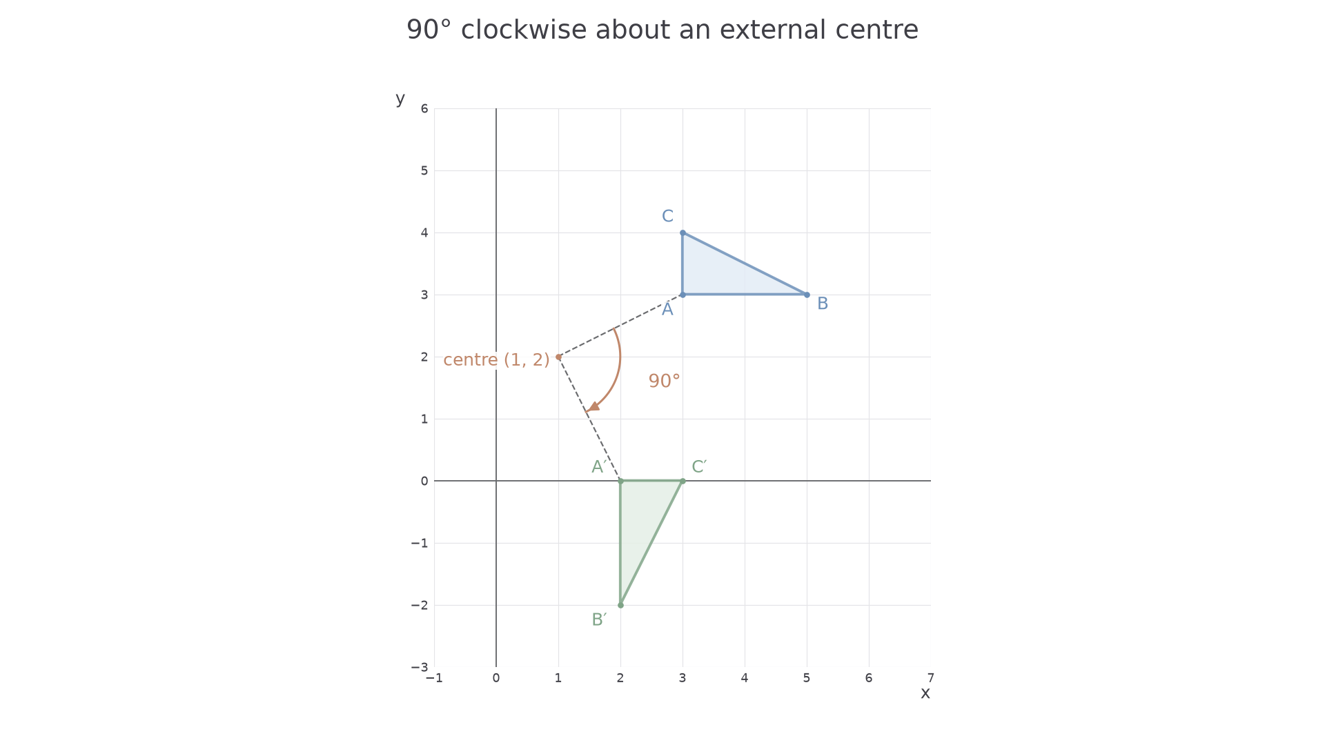
Worked example 3: an external centre
Question. Rotate through clockwise about .
Plan. Subtract the centre, use , then add the centre.
Answer. Rule the triangle through .
Check. The squared distances from the centre are respectively before and after the turn. Turning each image offset anticlockwise restores its original offset.
Keep the centre and triangle; change only the direction.
Worked example 4: reversing the turn
Question. Rotate the same triangle through anticlockwise about .
Plan. Use the same offsets, now turned by .
Answer. , joined with ruled sides.
Check. These images and the clockwise images lie on opposite sides of the centre, with their pairwise midpoints all . That fits the difference between the two turns.
To recover an unknown centre for a quarter-turn, choose two non-parallel point–image joining segments and draw their perpendicular bisectors. Their unique intersection is the candidate centre, because it is equally far from each point and its image. If two chosen bisectors coincide, use another vertex pair instead. Verify the stated turn for all vertices. For a half-turn, the midpoint of every pair gives the centre directly.
Watch out
Equal distances from a candidate centre are necessary but do not determine the angle or direction. Check that every pair makes the same stated turn before giving a full description.
Continue this lesson.
You’re previewing NovaLearn without an account. Create a free account to read the rest.
Create free account