C4.1, C4.3; E4.1, E4.3 - Scale drawings and bearings
A plan can put a long journey on one page, but distance alone does not locate the destination. You will draw and interpret lengths to scale, use three-figure bearings to give directions, and find the bearing for a return journey.
Reading and drawing to scale
You travel from a harbour to a buoy on a bearing of . Why is the bearing back , rather than ? A drawing will make the turn clear. First decide how much real distance each length on the drawing represents.
A scale drawing represents every length using the same multiplier. If represents , a line represents . Doubling the drawing length doubles the real length. A scale of expresses both lengths in the same unit: represents .
You already know
Proportion keeps a constant multiplier. Convert units first if using a ratio scale; is , not .
To draw a real length, divide by the amount represented by one drawing unit. To interpret a drawing length, multiply by that amount. Label the scale, rule straight edges, and keep enough room on the paper.
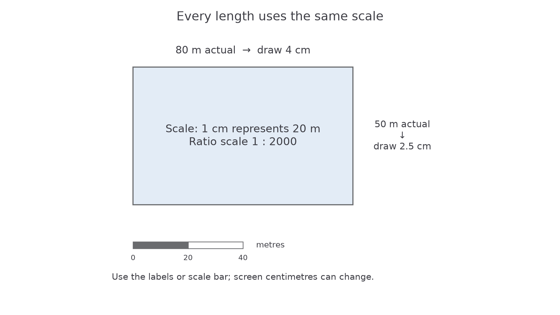
[DIAGRAM: asset_name: Scaled rectangular plan; asset_slug: scale_drawing_plan; caption: All lengths use the same scale; a scale bar survives screen resizing.; description: An exact rectangular plan is labelled actual length 80 metres and width 50 metres, with drawing instructions 4 centimetres by 2.5 centimetres at 1 centimetre to 20 metres. A proportional scale bar marked 0 20 and 40 metres is shown, and the note says use the labels or bar, not physical screen centimetres.]
Worked example 1: drawing a real distance
Question. A straight path is long. A plan uses to represent . Find the line length to draw. A second path measures on this plan; find its real length.
Plan. Divide by the scale value to draw a real length, and multiply to interpret a drawing length.
Answer. Draw the first path long on paper. The second path is long.
Check. , the required first distance. Also, , the given second measurement.
Keep the same path but change only the scale. More metres per centimetre means a shorter drawing.
Worked example 2: changing the scale
Question. Draw the same path using to represent . A second path measures on this plan; find its real length.
Plan. Divide to draw the first path, then multiply to interpret the second.
Answer. Draw the first path long; the second path is long.
Check. The scale represents twice as many metres per centimetre as before, so the same path occupies half the paper length. Also, .
For a full plan, convert every side using the same scale and preserve the required angles. For example, an by rectangular enclosure at to becomes by , with right angles drawn using a protractor or set square.
Watch out
“A line on my screen measures ” is not reliable scale information. Screen size and zoom change displayed centimetres. Use given lengths or compare with a scale bar that resizes with the diagram; measure a printed plan only when its print scale is guaranteed.
Use a labelled plan measurement, so there is no screen-size assumption.
Three-figure bearings from north
A bearing fixes the direction of a line by measuring a turn from north at the starting point. The words “from ” tell you where to put the protractor.
Three-figure bearing
The bearing of from is the angle measured clockwise from north at to the direction . Write it with three figures, such as , or .
Due north is (equivalently a full turn of ); due east is , due south is , and due west is .
[DIAGRAM: asset_name: Bearings measured clockwise from north; asset_slug: bearings_clockwise_from_north; caption: Both bearings start from north; the western bearing needs the longer clockwise turn.; description: Two exact compass diagrams show a ray at bearing 065 degrees and a ray at bearing 295 degrees. North is vertical in each, and clockwise arrows from north follow the correct short eastern turn and long western turn. The latter has a separate small counterclockwise angle of 65 degrees labelled not the bearing.]
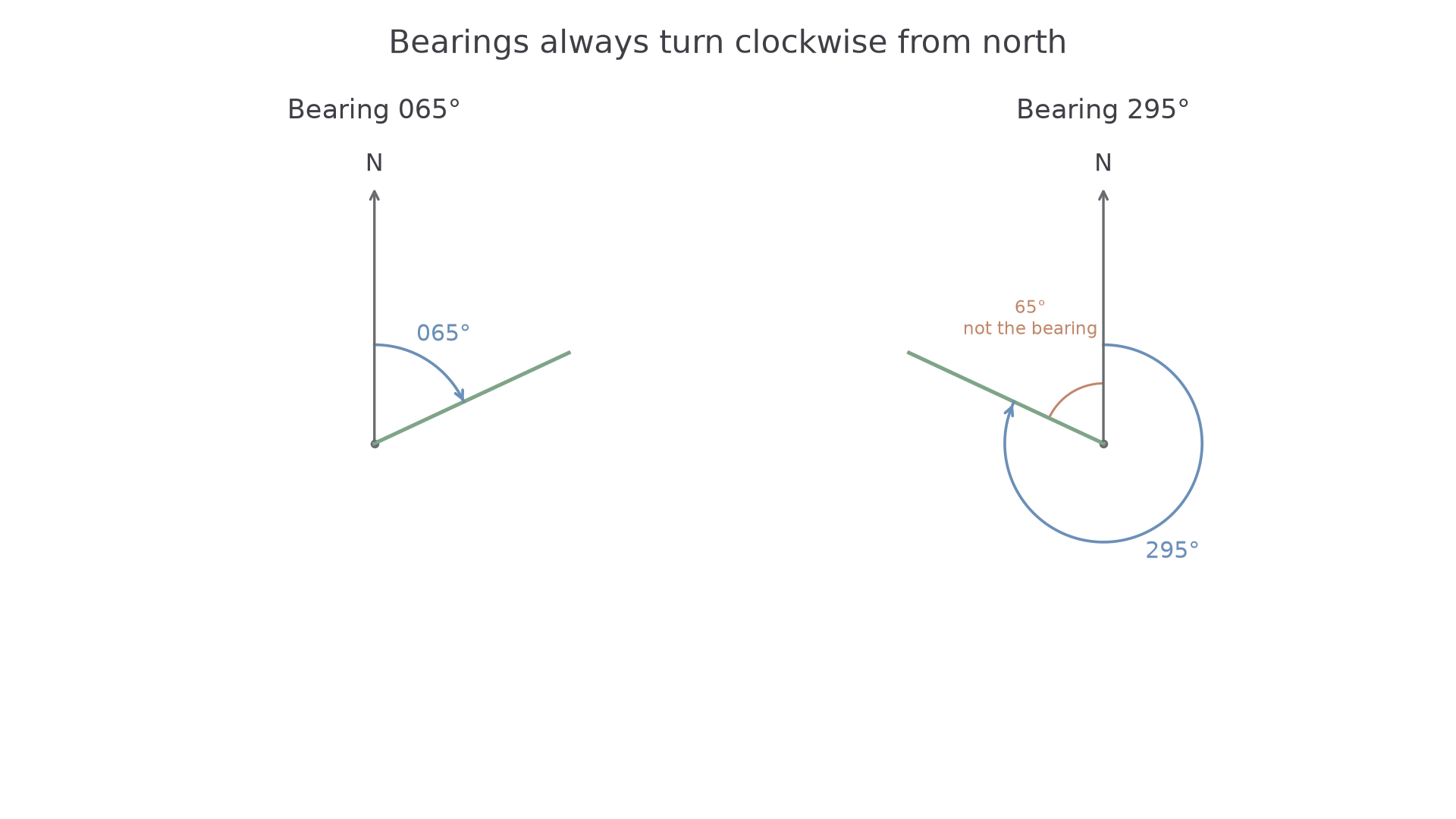
For a bearing below , a semicircular protractor can measure the clockwise turn directly on the eastern side of the north line. For a bearing above , either use a full-circle protractor or measure the smaller anticlockwise angle from north and subtract it from . This subtraction gives the required clockwise turn; it is not a reverse bearing.
Continue this lesson.
You’re previewing NovaLearn without an account. Create a free account to read the rest.
Create free account