Md15, Md16 - Equilibrium, sliding or toppling
Md15 combines zero resultant force with zero resultant moment to decide whether a rigid body can remain in equilibrium. Md16 checks the physical limits of that equilibrium: friction may run out, or the contact force may reach the edge of the supporting base, producing impending sliding or toppling.
Balance both forces and moments
Can making a surface rougher change a block's first failure from sliding to toppling? Extra friction can prevent slipping while the applied force still creates a turning effect. We need to check both limits, not assume that more friction guarantees equilibrium.
You already know
A particle requires zero resultant force for equilibrium. A rigid body also retains turning effects: a force has moment , with perpendicular distance , and a couple adds a signed moment without adding a resultant force.
Force balance prevents translational acceleration; moment balance prevents an unbalanced turning effect. A stationary rigid body needs both conditions at once.
Equilibrium of a planar rigid body
A rigid body is in equilibrium when its resultant force is zero and the sum of moments about any axis is zero. For coplanar forces, use
where the moment axis is perpendicular to the plane through a stated point . Given force balance, zero moment about one such point implies zero moment about every point.
Not in the formula booklet: learn it.
Choose a moment point that removes unknown forces passing through it. Then use force balance for the remaining unknowns. A support underneath a body can supply an upward normal reaction, but not a negative one; an algebraic negative answer means that contact assumption fails.
Worked example 1: two supports and a point load
Question. A uniform horizontal beam , length and weight , rests on supports at its ends. A downward load of is placed from . Find the upward support reactions.
Plan. Take moments about to eliminate its reaction, then balance vertical forces.
Why this step? The reaction at has zero moment about , leaving one unknown in the moments equation.
Answer. , .
Check. Their sum is . About , .
Change only the point load's position, from to from . The total load stays the same, while its turning effect changes.
Worked example 2: moving the point load
Question. Find the reactions when the load is instead from .
Plan. Use moments about again, then the unchanged total vertical load.
Why this step? A force's contribution to force balance does not change when moved along the beam, but its contribution to moment balance does.
Answer. , .
Check. Reflecting the arrangement in the beam's midpoint swaps the support reactions, exactly as the values show.
Force and moment equations have to describe the same body. Include the beam's own weight as well as any added load, at their separate positions.
Watch out
Wrong: use only and conclude that both reactions are .
Right: the moments equation decides how the load is shared. Equal reactions require the appropriate symmetry, not merely equal support heights.
The next load has a new magnitude at the first position.
What equilibrium reveals about the force system
Three non-zero coplanar forces in equilibrium must have concurrent or parallel lines of action. To see why, suppose two non-parallel lines meet at . Those two forces have zero moment about , so the third force's line must also pass through . If the forces are parallel, they may balance without sharing one point.
Concurrency or parallelism is necessary, not sufficient: the force magnitudes must still give zero resultant and zero moment. For two forces alone, equilibrium requires equal opposite forces on the same line.
If all applied forces have zero resultant but a non-zero total moment, an additional couple can supply the missing opposite moment. A couple cannot correct a non-zero resultant force.
Inferring an additional couple
If the known forces satisfy and have total signed moment , equilibrium requires an added couple of signed moment
Because the force resultant is already zero, this value is independent of the reference point.
Not in the formula booklet: learn it.
Keep a chosen moment sign throughout, and use the couple's units . It is a turning effect, not another vertical force.
Worked example 3: forces balance but moments do not
Question. A rigid body is acted on by upward forces at and at , and a downward force at . Determine the additional couple required for equilibrium.
Plan. Check force balance, then calculate the signed moment about , taking anticlockwise as positive.
Why this step? Adding another force would disturb force balance. A couple changes the moment without changing the zero resultant.
Answer. A clockwise couple is required.
Check. About , the forces give anticlockwise, confirming the same required couple.
Change only the downward force's position to . The force resultant stays zero, but the residual moment reverses.
Worked example 4: the required couple reverses
Question. Determine the required couple when the same downward force acts at .
Plan. Retain force balance and recalculate the moment about .
Why this step? The required couple opposes the calculated moment, rather than automatically being clockwise.
Answer. A anticlockwise couple.
Check. Adding it gives total moment , without changing any force component.
The added couple must cancel the residual moment, including its sign.
Watch out
Wrong: in the second example. That reinforces the existing clockwise moment instead of cancelling it. Correct: , anticlockwise with the chosen sign convention.
These three forces are parallel in both examples, yet still need an added couple. That is a concrete reason not to treat the three-force geometry condition as a complete equilibrium test.
Exam tip
State the reference point and the positive turning sense before a moments equation. A clockwise couple has the same clockwise effect about every point; its sign does not change when your pivot moves.
The next system also has zero resultant force, leaving its moment as the deciding calculation.
A pushed block has two different thresholds
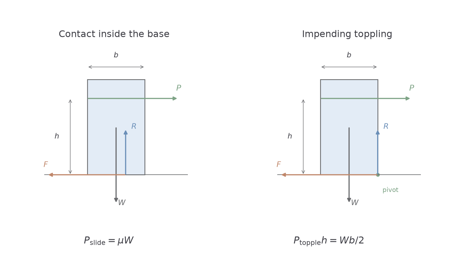
Model a uniform upright block on rough horizontal ground. Its weight acts through the geometric centre. A horizontal push acts at height , and its base has width in the push direction. Increase slowly from zero, so the question is which static equilibrium condition fails first.
Vertical and horizontal balance give and required friction . Sliding is impending at . Meanwhile the resultant normal contact can move towards the leading edge of the base, but cannot move beyond it.
[DIAGRAM: asset_name: Sliding and toppling thresholds for a pushed block; asset_slug: h645_b059_push; caption: Sliding exhausts friction while toppling moves the contact resultant to the leading edge; description: A uniform upright block on horizontal rough ground has base width b, downward weight W through its centre, and rightward push P at height h. Leftward friction and upward normal reaction act at the ground. A separate limiting diagram places both contact components at the lower right pivot. Dimensions mark the width b and push height h. Equations show P slide equals mu W and P topple times h equals W b over two.]
Continue this lesson.
You’re previewing NovaLearn without an account. Create a free account to read the rest.
Create free account