AN10–AN12 - Network flows and cuts
Model transmission through capacity-limited directed arcs. AN10 checks feasible flows and introduces super sources and sinks, AN11 calculates cut capacities, and AN12 certifies a maximum flow by matching it to a cut of the same value.
Separate flow from capacity
One pipe in a transmission system is full. Does that prove the whole system is carrying its maximum possible flow? A full pipe may sit beside unused alternatives. To prove a maximum, we need a bound on the whole system as well as a feasible flow.
You already know
A directed network gives permitted directions and weights with a stated meaning. A model must identify what each vertex and arc represents; reversing an arrow changes a permitted connection.
Think of fluid moving steadily from a source to a sink , with no losses or accumulation inside the network. The same mathematics can describe data transmission or traffic rates when the model's assumptions are appropriate.
Capacity and feasible flow
An arc's capacity is its maximum permitted rate. Its flow is the actual assigned rate. A feasible flow satisfies on every directed arc and flow in equals flow out at every vertex other than the source and sink. An arc is saturated when its flow equals its capacity.
The value of the flow is the net rate leaving , equal to the net rate entering . In the examples below no arcs enter or leave , so add the flows leaving , or add those entering . Do not add the flows on every arc: the same fluid may pass through several arcs.
All these flow relations are modelling rules, not supplied formula-booklet results. Keep capacity and assigned flow in separate tables or use a clearly stated label such as “flow/capacity”.
Complete a feasible flow using conservation
Use a separate equation at each intermediate vertex. A reverse-direction arc is a separate permitted pipe, so include it on the correct side of the conservation equation.
Conservation and total value
For every intermediate vertex ,
Check after solving. With no incoming arcs at or outgoing arcs at ,
Not in the formula booklet: learn it.
The following directed system has capacities in litres per minute.
| Arc | ||||||
|---|---|---|---|---|---|---|
| Capacity |
[DIAGRAM: asset_name: Capacity and a feasible assigned flow; asset_slug: flows_capacity_and_assignment; caption: Arc limits and actual assigned rates are different data, and both internal vertices must conserve flow; description: A directed network has S at left, A upper middle, B lower middle and T at right. Arc capacities are SA 8, SB 6, AB 3, BA 2, AT 5 and BT 9. A second panel labels the feasible assigned flows SA 7, SB 5, AB 3, BA 1, AT 5 and BT 7, all in litres per minute. The opposite AB and BA arcs are drawn separately with distinct arrowheads and labels.]
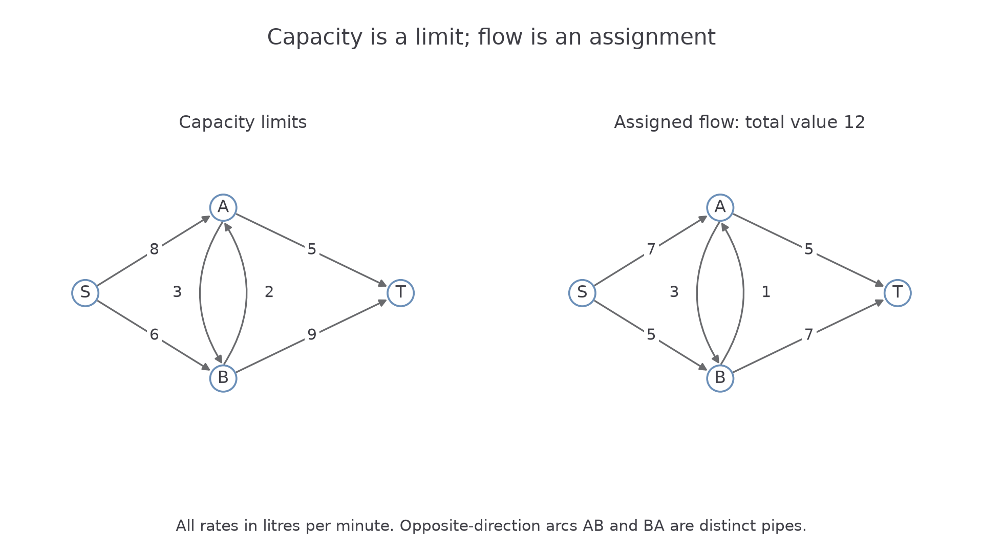
Worked example 1: solve two missing rates
Question. In this system the assigned flows are . Determine , and the total flow value, checking feasibility.
Plan. Balance vertex , then vertex , and check the assigned rates against the capacities.
Why this step? Flow enters but leaves , so it appears on opposite sides of the two equations.
Answer. , , total value . Every flow is non-negative and no capacity is exceeded.
Check. and are saturated, but other pipes have spare capacity; saturation alone does not establish a maximum.
Change only the assigned flow from to . Keep .
Worked example 2: a different feasible assignment
Question. Complete this revised flow and determine its value.
Plan. Reapply the same conservation equations with the changed source contribution.
Why this step? A changed incoming rate must propagate through the conservation equations; it cannot simply disappear at an intermediate vertex.
Answer. , , total , within all capacities.
Check. The sink receives , agreeing with the source output.
If the equations force an arc above capacity, the given partial assignment has no feasible completion. Conservation is necessary, but does not replace the capacity check.
Watch out
Wrong: conservation at is in the revised assignment. Flow enters ; it does not leave it. Correct: , giving , followed by a separate balance at .
Classify each directed flow as incoming or outgoing before writing the next balance.
Specify a cut and count its forward capacity
A cut splits the vertices into two sets: one contains , the other . To transmit flow from source to sink, the net flow must cross from the source side to the sink side somewhere.
Cut capacity
For a partition with and , the cut capacity is the sum of the capacities of arcs directed from to . Do not include arcs pointing from back to , and do not subtract their capacities.
Specify both vertex sets or clearly list the crossing arcs. Use the original capacity diagram, not the numbers in a particular assigned-flow diagram.
A cut gives an upper bound
For every feasible source-to-sink flow and every source–sink cut,
The net flow equals forward crossing flow minus reverse crossing flow. Forward flow is at most its forward capacities, while reverse flow is non-negative.
Not in the formula booklet: learn it.
Use the original capacity table .
Worked example 3: a cut with a backward arc
Question. Calculate the capacity of , .
Plan. Classify each crossing direction before summing capacities.
Why this step? counts here because is on the source side; its letter order alone says nothing about the cut direction.
Answer. Cut capacity , giving upper bound .
Check. stays within , and within , so neither crosses the cut.
Change only the partition to , . The network itself is unchanged.
Worked example 4: a stronger cut bound
Question. Calculate this cut's capacity and compare the resulting upper bound.
Plan. Reclassify forward and backward crossings for the new sets.
Why this step? A cut's capacity depends on the partition. A smaller capacity gives a stronger upper bound, but is not automatically known to be the minimum cut.
Answer. Capacity , so , stronger than .
Check. For the earlier feasible value , the net crossing flow is ; the backward flow is subtracted in this check, unlike backward capacity in the capacity sum.
One identified cut bounds every feasible flow. You do not have to exhaustively list all cuts to produce a useful bound or a maximum-flow certificate.
Watch out
Wrong: the second cut has capacity . Backward crossing capacity is neither added nor subtracted in a cut capacity. Correct: ; subtract backward flow only when checking the net assigned flow.
List only forward cut arcs before summing the next capacities.
Continue this lesson.
You’re previewing NovaLearn without an account. Create a free account to read the rest.
Create free account