Paper 5 - Planning a workable investigation
Learn to turn a proposed relationship into a complete, workable investigation. Choose variables and measurements, explain the procedure with a labelled apparatus arrangement, and show how the results would test the relationship and determine its constants.
A question the measurements can answer
If you double a wire's length, must your measured resistance double? The wire itself may obey a proportional relationship, while contacts add an extra resistance. A good investigation can distinguish those possibilities instead of assuming its answer before collecting data.
Paper 5 has two 15-mark questions: an experimental plan, then a structured analysis of supplied data. The plan needs a diagram and connected writing explaining what you would actually do. Its marks reward specific practical and analytical points, not essay length. These lessons practise the written skills; effective preparation also requires repeated cycles of planning, performing and evaluating real experiments under a teacher's supervision.
Consider this proposed model:
Here measured resistance is in ohms, active wire length in metres, wire cross-sectional area in square metres, resistivity in , and a constant contact contribution in ohms. The relationship is supplied for this investigation; do not assume a general formula sheet for Paper 5. It predicts a straight line, but a line through the origin only if the contact contribution is negligible.
The independent variable is the quantity deliberately changed: . The dependent variable is the measured response: , determined from voltage and current. The controlled quantities include wire material, cross-sectional area and temperature, since changing any of them could change resistance independently of length. Write what is kept constant; “control the temperature” alone does not say whether you intend to hold it constant or vary it.
Before measuring, choose a range that can reveal a trend. A preliminary trial might show that lengths from to , at roughly intervals, produce measurable voltages without overheating. Those values are a justified starting proposal, not a rule for every wire. Very short lengths make a fixed contact contribution and length uncertainty relatively large; excessive current changes the temperature you meant to keep constant.
Key idea
A hypothesis states the predicted pattern and conditions. A procedure supplies measurements that could disagree with it. Never force a graph through the origin simply because proportionality would be convenient.
An arrangement that yields the required data
A list of equipment is only a start. Your arrangement must let you vary the intended length, measure the voltage across that same length and measure its current. A beautiful circuit that measures a different piece of wire will give the wrong investigation very neatly.
[DIAGRAM: asset_name: Measuring resistance over a variable wire length; asset_slug: practical-a2-wire-plan; caption: The sliding contact defines both the active length and the voltage-measurement endpoint; description: A complete isolated low-voltage circuit has a supply, switch, variable resistor, series ammeter and a resistance wire mounted straight along a metre rule. A fixed contact and a sliding contact define the active wire length L. A voltmeter is connected across those same two contacts, and the unused portion of wire extends beyond the sliding contact.]
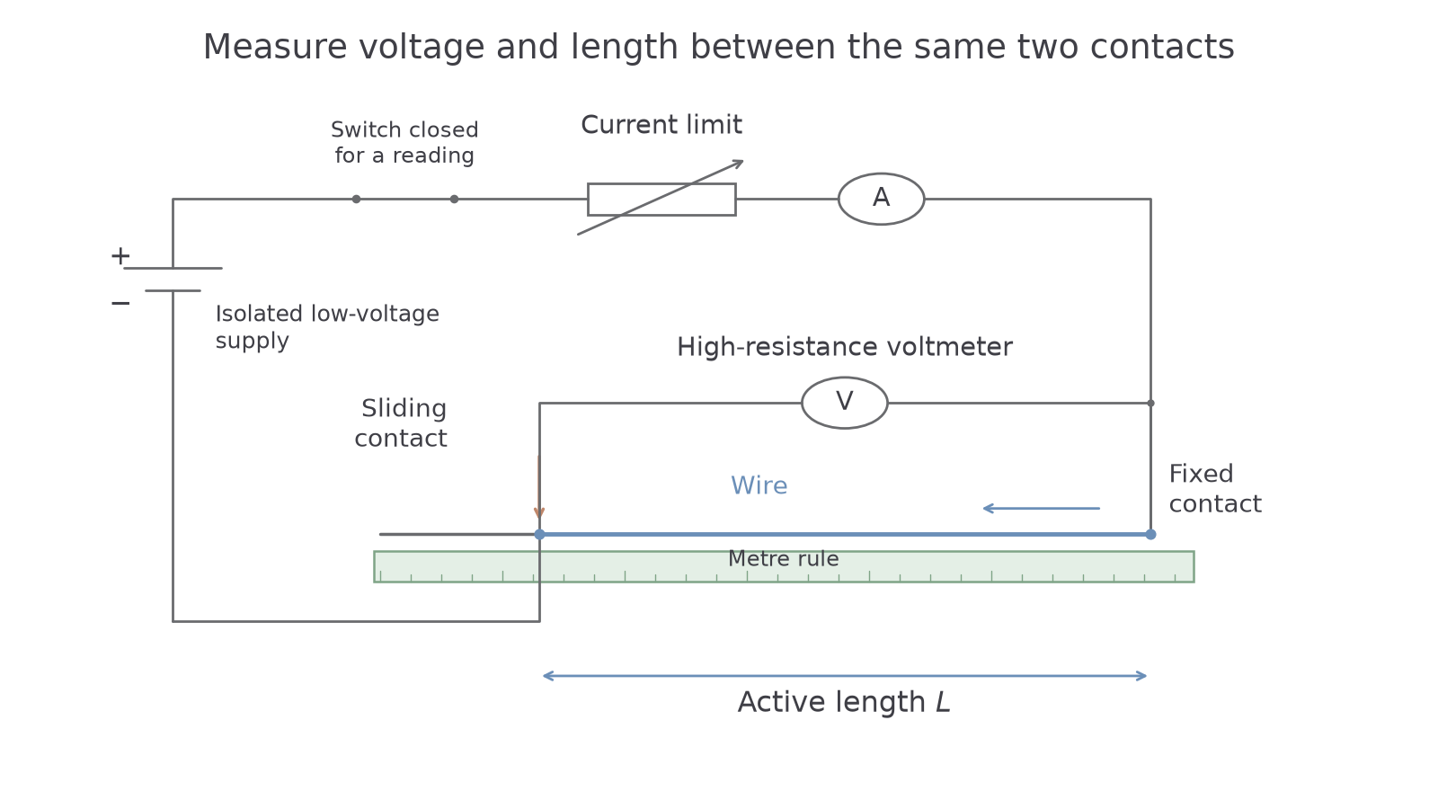
Fix a uniform wire straight alongside a metre rule without stretching it. Connect one end to a low-voltage supply through a switch, current-limiting variable resistor and ammeter. A sliding contact returns current to the supply and selects . Connect the voltmeter between the fixed contact and the sliding contact. Mark the two points from which length is measured: is the difference of their rule readings, not the position of an arbitrary clip edge. Keep the contact method and contact pressure as consistent as practicable.
For each selected length, close the switch briefly, read across the active length and the simultaneous series current , then open the switch. Calculate . The voltmeter should have a high input resistance so its current is negligible compared with the wire current. Adjust the series resistor if necessary to keep current suitably small; record the actual current rather than assuming the supply setting makes it constant.
Choose meter ranges from trial readings. A – range resolving may be suitable for voltages around –, whereas a range too large wastes resolution. A current meter must resolve changes meaningfully without overloading. Quote instrument resolution honestly; it does not by itself describe all uncertainty, such as fluctuating contacts or temperature drift.
Measure diameter with a micrometer at several positions and orientations, checking zero first and using the ratchet gently. Calculate the mean diameter and , converting to metres before finding area in square metres. These area relations must be recalled; they are not assumed supplied for this plan. A ruler is suitable for a length of several tenths of a metre but unsuitable for a wire diameter of a fraction of a millimetre.
Continue this lesson.
You’re previewing NovaLearn without an account. Create a free account to read the rest.
Create free account