10.1 - Circuit diagrams and electromotive force
Learn to read and draw Cambridge's circuit symbols, place measuring instruments correctly, and describe a source's electromotive force in terms of energy per unit charge. Distinguish that energy supply from the energy transferred in a component without treating current as something the circuit consumes.
Symbols and connected circuit diagrams
Why can the same current pass through a cell and a lamp even though the lamp transfers energy to its surroundings? The circuit does not use up charge. A complete conducting path allows charge to flow, while the source and lamp transfer energy in different directions. A circuit diagram makes those connections clear without trying to draw the apparatus to scale.
A line represents a connecting conductor. A solid dot marks a junction where conductors join. Wires crossing without a junction dot are not connected in the usual diagrams used here; check any explicit bridge or connection marking. The position of a component on the page does not determine whether it is in series or parallel: trace the connections.
Sources and measuring instruments
[DIAGRAM: asset_name: Sources and meters; asset_slug: circuits-symbols-sources-meters; caption: The source and instrument symbols used in Cambridge circuit diagrams; description: A nine-symbol key shows a cell, battery of cells, power-supply terminals, alternating-current power supply, earth connection, ammeter, voltmeter, galvanometer and oscilloscope. Each symbol is redrawn in the Cambridge form and labelled.]
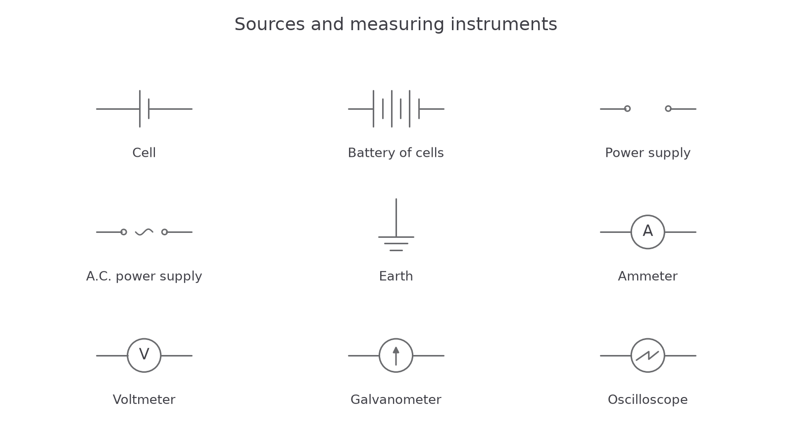
A cell has one long line and one short line; the long line is the positive terminal. A battery of cells uses repeated cell pairs. A power supply can be represented by two output terminals; an a.c. supply adds an alternating-wave mark. An earth symbol identifies an earth connection or reference where shown; it is not a symbol for a cell's negative terminal in every circuit.
An ammeter, a circle containing A, measures current and is connected in series with the branch being measured. An ideal ammeter has negligible resistance. A voltmeter, a circle containing V, measures potential difference between two points and is connected across them. An ideal voltmeter has infinite resistance and draws no current. Real instruments only approximate these models.
A galvanometer is a sensitive current detector, shown with an arrow inside a circle. It can detect zero current and the direction of a small current, which becomes useful in null methods. An oscilloscope, a circle with a trace inside, measures a voltage between its input connections; its display also shows how that voltage changes with time.
Switching, resistance and light
[DIAGRAM: asset_name: Switching and resistive components; asset_slug: circuits-symbols-resistance-light; caption: Arrows, slashes and extra terminals distinguish these related symbols; description: A nine-symbol key shows a junction of conductors, switch, lamp, fixed resistor, variable resistor, thermistor, light-dependent resistor, heater and potentiometer, using the Cambridge rectangular resistor convention.]
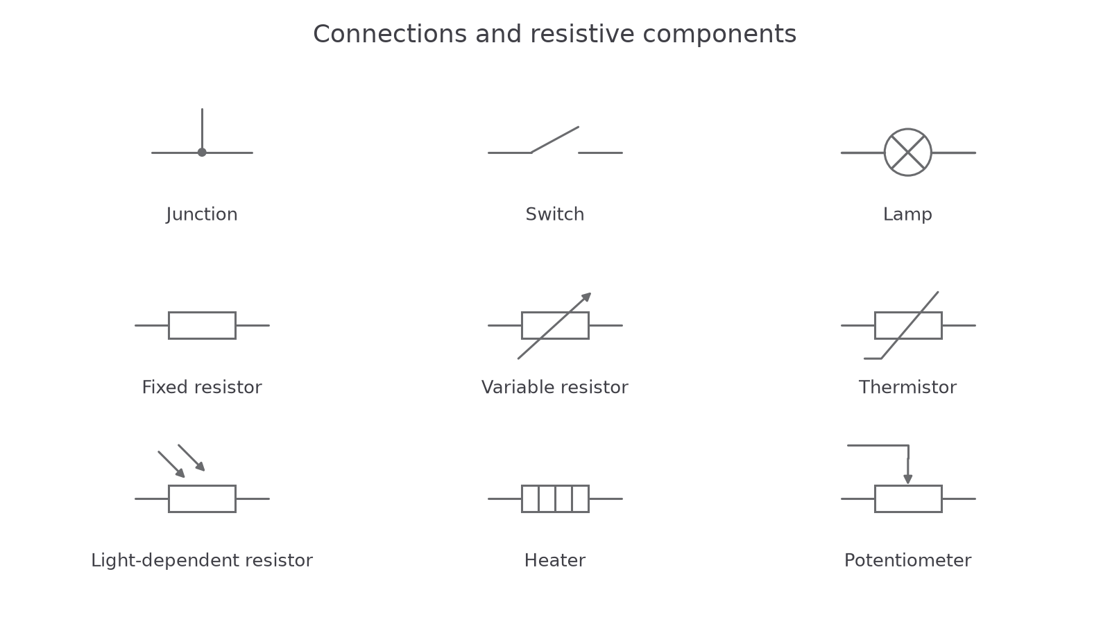
An open switch shows a gap; closing it joins the contacts. A lamp is a circle with a cross. A fixed resistor is a rectangle. A variable resistor adds a diagonal arrow through the rectangle and is used to vary resistance. A thermistor has the temperature-dependent resistor mark: a diagonal stroke with a short bent end, rather than a variable-resistor arrow. A light-dependent resistor, or LDR, has arrows pointing towards the resistor to represent incident light. A heater uses the segmented rectangular symbol. These devices transfer electrical energy in different ways; the resistor symbol alone does not promise a particular numerical resistance.
A potentiometer has a resistor track with a third, sliding contact shown by an arrow onto the track. Its three-terminal use lets you select a fraction of an applied p.d.; connecting only a suitable end and slider instead gives a variable resistance.
Sound, motion and semiconductor components
[DIAGRAM: asset_name: Output devices and semiconductor symbols; asset_slug: circuits-symbols-other-devices; caption: Recognise the complete prescribed symbol set, including devices whose operation is studied later; description: A nine-symbol key shows an electric bell, buzzer, microphone, loudspeaker, motor, generator, diode, light-emitting diode and capacitor in their Cambridge forms.]
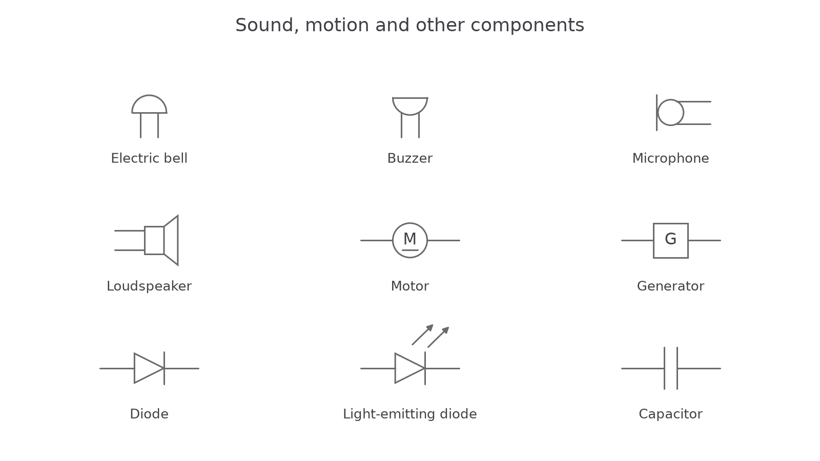
The electric bell and buzzer have the prescribed dome and inverted-dome shapes. A microphone converts sound variations into an electrical signal; a loudspeaker does the reverse. A motor has M in a circle; a generator has G in a square. A diode has the triangular/line symbol shown; its forward direction is towards the line. A light-emitting diode, or LED, adds arrows pointing away to show emitted light. A capacitor is represented by two parallel plates separated by a gap; do not join the plates with a wire. You will study its charging behaviour at A Level.
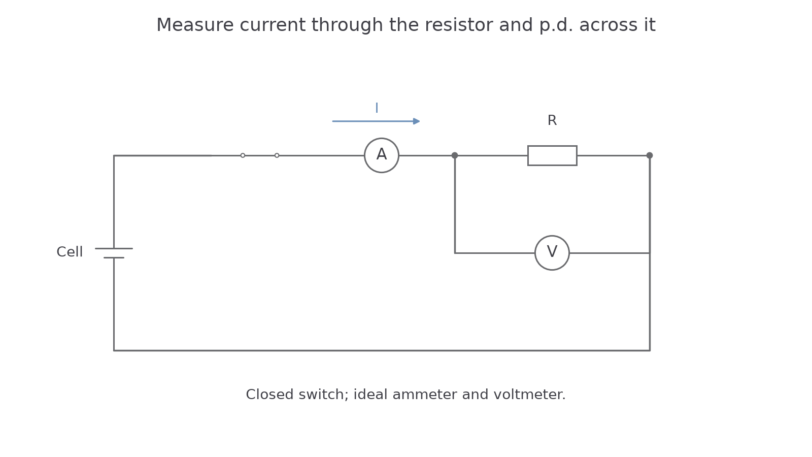
Use these symbols to communicate connections, rather than sketching recognisable household objects. For example, to measure a resistor's current and p.d., place the source, switch, ammeter and resistor in one closed loop. Connect the voltmeter between the two resistor terminals.
[DIAGRAM: asset_name: Current through, voltage across; asset_slug: circuits-meter-connections; caption: The ammeter is in series; the voltmeter bridges the resistor's two terminals; description: A closed cell–switch–ammeter–resistor circuit has an ideal voltmeter connected in parallel across the resistor only. Junction dots show its two connections. The cell's long positive plate connects to the ammeter side; a conventional-current arrow runs from positive through the external resistor towards negative.]
Watch out
An ammeter across a cell creates a very low-resistance path and can damage equipment. A voltmeter in series would greatly reduce the current. Decide whether you need the current through a branch or the p.d. between two points before wiring the meter.
Continue this lesson.
You’re previewing NovaLearn without an account. Create a free account to read the rest.
Create free account