20.5 - Faraday's law and Lenz's law
Connect induction experiments to the rate of change of magnetic flux linkage. Calculate induced e.m.f. from changes and graph gradients, then use Lenz's law to determine its direction and explain the required energy transfer without confusing e.m.f. with current.
What changes in an induction experiment
Why does a galvanometer connected to a coil deflect while a magnet moves towards it, then return to zero when the magnet is held still? The magnetic field is still present when the magnet is stationary. What has stopped is the change in the coil's magnetic flux linkage.
Connect a coil to a sensitive centre-zero galvanometer in a complete circuit. Move a bar magnet towards the coil along its axis, then hold it still and withdraw it. The meter deflects during approach, returns to zero at rest, and deflects the opposite way during withdrawal. It detects an induced current driven by an induced electromotive force, or e.m.f.
[DIAGRAM: asset_name: Magnet and coil induction experiment; asset_slug: magnet-coil-induction-experiment; caption: Motion changes linkage and drives a current around the closed measuring circuit; description: A bar magnet with its north end facing right moves towards a coil. Both coil ends connect by separate wires to the two terminals of a centre-zero galvanometer, completing one circuit. Three adjacent labelled observations give approach deflection, stationary zero, and withdrawal opposite deflection; the sign is relative and depends on chosen connections.]
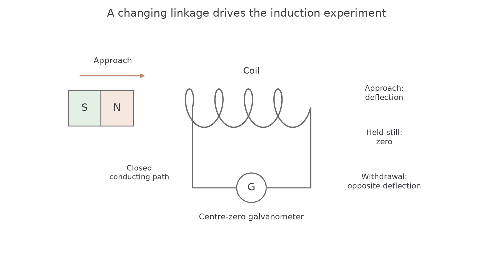
Repeat using the same magnet, path and endpoints but a faster movement. The linkage changes in less time, giving a larger peak e.m.f. A stronger magnet, closer magnetic coupling, or more turns linking the same changing flux can also increase the e.m.f. Keep the other factors controlled when comparing one change.
A galvanometer measures current, so its deflection also depends on circuit resistance and the meter's response time. Replacing the coil with one having more turns may also change resistance. To compare e.m.f. directly, use a suitably sensitive high-input-resistance voltmeter or oscilloscope across the coil and record the voltage pulse. Do not interpret every current increase as proof of a larger e.m.f. without controlling the circuit.
Watch out
An induced e.m.f. can exist across an open coil. A sustained conduction current needs a closed conducting circuit. “No current” does not by itself mean “no induced e.m.f.”
Motion is one way to change flux linkage, not a requirement of induction. Keep a small pickup coil stationary inside a solenoid and change the solenoid current: the changing field changes the pickup coil's linkage. A constant solenoid current gives a steady field and no continuing induced e.m.f. in the stationary pickup coil. Rotate a coil in a steady field and its projected area changes instead.
These comparisons identify the cause: linkage can change because field strength, linked area or orientation changes. A large but unchanging linkage is insufficient. A straight conducting bar with its length, velocity and magnetic field mutually perpendicular offers another view: magnetic deflection separates its mobile charges along the bar and establishes a terminal e.m.f.; an external conducting path is still needed for a continuing current.
Practical: a fair comparison of speed
Use a fixed pickup coil and the same magnet, with a guide marking a repeatable path and endpoints. Connect the coil to an oscilloscope with a suitable voltage and time scale. Record several passes at each intended speed and compare the peak voltage magnitudes and pulse widths. Faster passes should give taller, narrower pulses for the same linkage change.
Keep magnet orientation, distance, coil position and turn count unchanged. A mechanical guide improves repeatability; inconsistent hand alignment changes the linked field as well as speed. Keep fingers clear of moving magnets and avoid letting a strong magnet strike the coil or nearby magnetic equipment.
The experiment establishes a pattern. Faraday's law will make that pattern quantitative, and Lenz's law will explain the reversal.
Rate of change sets the induced e.m.f.
A coil can undergo the same total linkage change slowly or quickly. The quicker change gives the greater e.m.f. because the induced e.m.f. depends on a rate, not merely on the initial or final field strength.
Faraday's law
The induced e.m.f. is proportional to the rate of change of magnetic flux linkage.
The complete linkage must include the turns. If denotes flux through one turn and is constant, use ; if a graph already gives total linkage, do not multiply by again.
Signed induced e.m.f.
is induced e.m.f. in volts, signed flux linkage in webers and time in seconds. The first expression is the instantaneous negative graph gradient; the second gives the average over a stated interval. Choose the positive loop direction and associated positive normal consistently. For magnitude alone, use the magnitude of the rate of change.
Not on the data sheet: learn it.
The sign convention follows a right-hand link: curl your fingers around the chosen positive circuit direction, and your thumb gives the positive area normal. For a loop in the page, anticlockwise is associated with a normal out of the page. An increase of positive outward linkage then gives negative, clockwise e.m.f. The minus sign expresses opposition to change, not a rule that every measured voltage must be negative.
A weber per second is a volt. On a graph with linkage in milliwebers and time in milliseconds, the two factors of a thousand cancel when finding a gradient in volts. Write the units carefully rather than treating all graph axes as SI automatically.
Worked example 1: decreasing positive linkage
Question. Relative to a fixed positive normal, a coil's linkage falls from to in . Determine its average signed e.m.f.
Plan. Find final minus initial linkage, then apply Faraday's minus sign.
Answer. in the chosen positive circuit direction.
Check. The linkage is decreasing, so the induced direction tends to maintain its positive sense.
[DIAGRAM: asset_name: Linkage gradient and induced voltage; asset_slug: linkage-and-induced-emf; caption: E.m.f. is the negative gradient, not the height, of the linkage graph; description: Aligned graphs show linkage in milliwebers increasing from zero to six between zero and two milliseconds, constant from two to five milliseconds, and decreasing to zero from five to eight milliseconds. The induced e.m.f. is minus three volts on the rising section, zero on the flat section and plus two volts on the falling section. Sharp corners are identified as an idealisation.]
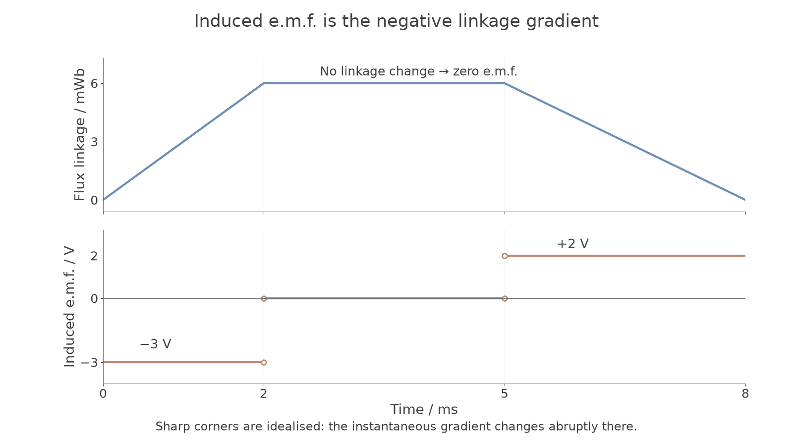
For a curved linkage graph, draw a tangent at the required time and determine its gradient. Maximum e.m.f. magnitude occurs where the graph is steepest, not where its height is greatest. If a graph gives while coil area and orientation are fixed, multiply its gradient by for a perpendicular coil. For sinusoidal linkage, its extrema have zero gradient and therefore zero induced e.m.f. at those instants.
Continue this lesson.
You’re previewing NovaLearn without an account. Create a free account to read the rest.
Create free account