9.3, 10.3 - Potential dividers and sensors
Learn how two series resistances divide a fixed supply p.d., why a connected load can change the output, and how thermistors and light-dependent resistors turn environmental changes into voltage changes. Always identify the two points between which the output is measured.
Dividing a supply p.d.
Why can a divider give to a voltmeter but only after a load is connected? The voltage has not been used up. The load changes the circuit's resistance arrangement, so it changes the fraction of the supply appearing at the output.
A potential divider has two resistances in series across a supply. With no significant output current, the same current flows through both. Take as the upper resistor and as the lower resistor; measure the output from their junction to the lower supply terminal. The output is then the p.d. across , rather than across the whole pair.
Using the series resistance and resistance definitions,
Combining them gives the useful fraction.
Unloaded potential divider
Supply p.d. and output p.d. are in volts; resistances and use the same unit. This output is across . The relation assumes negligible output current, for example an ideal voltmeter, and a fixed supply p.d.
Not on the data sheet: learn it.
Worked example 1: choosing the output resistor
Question. A supply is connected across and in series. Determine the p.d. across the resistor, measured by an ideal voltmeter.
Check. The smaller resistor receives the smaller p.d. The current is ; multiplying by confirms .
A real load bridges the same two output terminals as the lower resistor, so it is in parallel with that resistor. Replace the parallel pair before using the divider fraction. A high-resistance voltmeter has little effect; a low-resistance load can have a large one.
[DIAGRAM: asset_name: A divider with a connected load; asset_slug: circuits-loaded-divider; caption: The load is in parallel with the lower resistor, changing the divider fraction; description: A complete ideal 12-volt supply circuit has an upper 3.0-kilohm resistor and lower 6.0-kilohm resistor. A 6.0-kilohm load connects between the middle junction and the lower supply node, in parallel with the lower resistor. An ideal voltmeter bridges the same output nodes.]
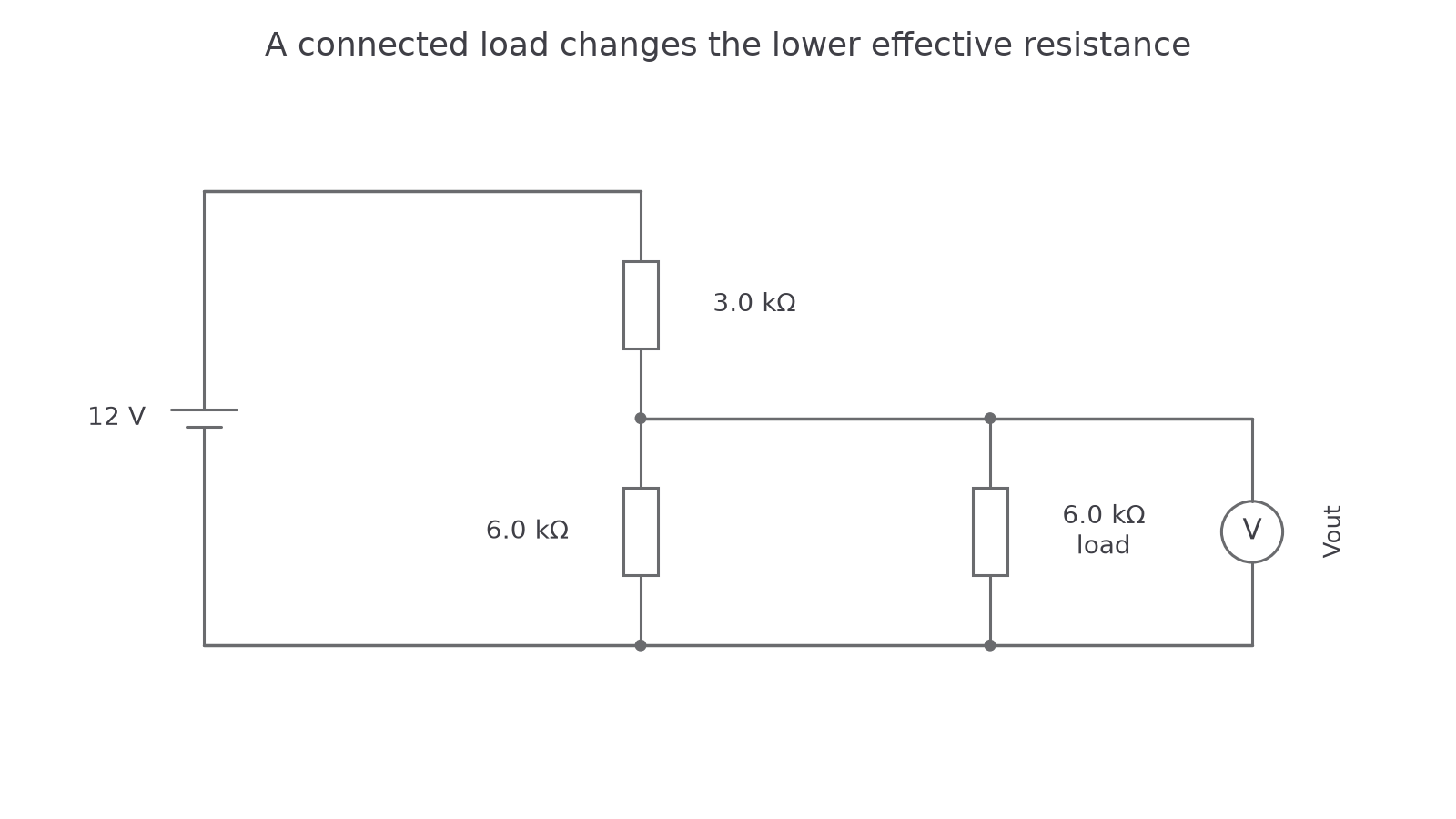
Exam-style example: the output changes under load
Question. A supply has upper resistance and lower resistance . Compare the unloaded output with the output when a load bridges the lower resistor. Use for the parallel combination.
Check. The lower effective resistance has decreased. It receives a smaller fraction of the fixed supply, explaining the opening readings.
Watch out
The numerator is the resistance between the actual output terminals. “The top resistor” or “the sensor” is not a universal numerator. Trace the two measurement connections first.
Apply the fraction to a different pair.
Temperature-dependent voltage
A resistor whose resistance changes with temperature can make a divider's output respond to temperature. The thermistors in this course have a negative temperature coefficient: their resistance decreases as temperature rises.
This is different from the metallic filament you studied earlier, whose resistance increases as it becomes hotter. Do not transfer the filament explanation to a thermistor simply because both are components that warm up. The thermistor's semiconductor material gives a different resistance–temperature response.
[DIAGRAM: asset_name: Sensor position controls output direction; asset_slug: circuits-sensor-dividers; caption: A top thermistor can give an output that rises with temperature; a lower LDR can give an output that falls with light intensity; description: Two separate complete divider circuits are shown. Left: fixed supply, upper NTC thermistor and lower fixed resistor, with an ideal voltmeter across the lower resistor. Right: fixed supply, upper fixed resistor and lower LDR, with an ideal voltmeter across the LDR. Each output's two terminals are marked and the LDR's light arrows point towards it.]
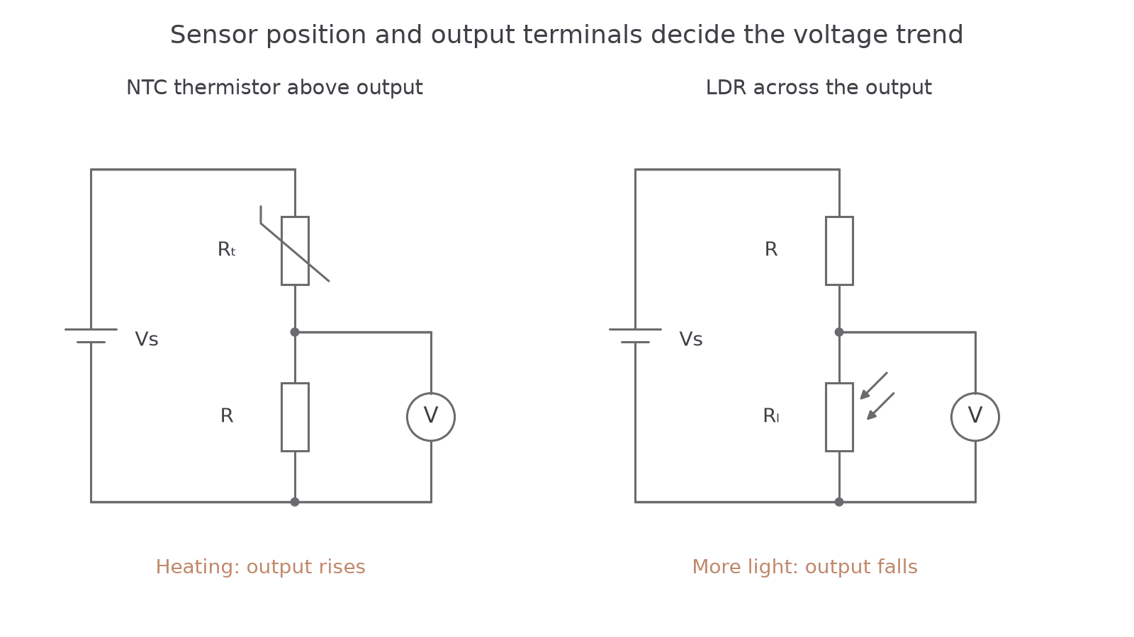
Put a thermistor above a fixed resistor , and measure the output across the fixed resistor. Heating reduces , reducing the total series resistance. Current rises, so the p.d. across the fixed resistor rises. Equivalently, has a decreasing denominator and a fixed numerator.
Continue this lesson.
You’re previewing NovaLearn without an account. Create a free account to read the rest.
Create free account