10.2 - Resistors in series and parallel
Derive the series and parallel resistance rules from Kirchhoff's laws, then use them to simplify connected resistor networks. Track total current, branch current and p.d. as separate quantities so that a simplified circuit can be translated back into the original one.
Series resistance from the loop law
How can adding a resistor make a circuit's total resistance smaller? It can happen when the added resistor provides another branch. First understand the contrasting arrangement: in series, every charge in the branch passes through both resistors, so their p.d.s add for the same current.
Two resistors are in series when they share a single current path with no intervening current split. Moving their symbols around on the page does not change that relationship. The equivalent resistance is the single resistance that would draw the same current at the same p.d. between the chosen external terminals.
For two series resistors, the current is the same through both by charge conservation. The loop law gives . Substituting the resistance relation,
The cancellation uses the same current in all three terms. Repeating the argument adds any further series resistances.
Resistors in series
All resistances are in ohms. The components must share the same current path; their p.d.s add. This relation does not apply merely because two resistors are drawn beside one another.
On the data sheet.
[DIAGRAM: asset_name: Series and parallel connections; asset_slug: circuits-series-parallel; caption: Series components share current; parallel branches share their two end nodes; description: Two separate complete ideal-source circuits compare two series resistors R1 and R2 with the same resistors on two parallel branches. In series, one arrow I labels the common current. In parallel, I splits into I1 and I2 at a junction, then rejoins. Each resistor branch connects to the same labelled A and B nodes.]
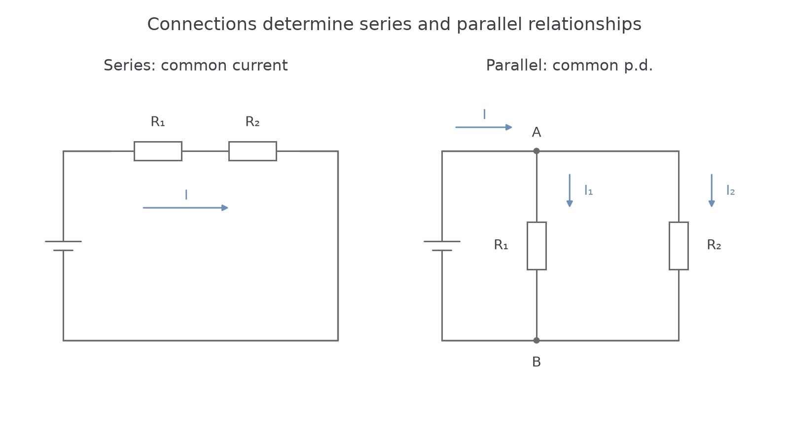
Worked example 1: p.d.s in a series path
Question. and resistors are in series across an ideal source. Calculate the current and each resistor's p.d. Use .
Check. The p.d.s sum to . The greater resistance has the greater p.d. because the current is common.
An extra series resistor increases equivalent resistance. At a fixed terminal p.d., that reduces the common current. If a real source's internal resistance is included, it is another series contribution in the complete current path, although it lies inside the source rather than the external load.
Parallel resistance from the junction law
Parallel branches connect between the same two nodes. They therefore have the same p.d., but can carry different currents. A charge can take either route; adding a conducting route makes the total current greater at a fixed terminal p.d.
Let the common p.d. be . The junction law gives . Using in each branch and in the equivalent circuit,
The common quantity cancelled here is p.d., rather than current. That difference is the reason the parallel rule contains reciprocals.
Resistors in parallel
All resistances are in ohms. Each resistor must bridge the same pair of nodes; its branch p.d. is then the common terminal p.d.
On the data sheet.
For exactly two resistors, rearranging gives . This shortcut is derived from the supplied reciprocal rule, rather than printed separately. Do not extend the two-resistor product-over-sum form unchanged to three resistors.
Worked example 2: calculate resistance and branch currents
Question. and resistors are in parallel across an ideal source. Find the equivalent resistance, branch currents and source current. Use .
Check. . The equivalent resistance is smaller than either branch resistance, as expected for two finite positive resistances in parallel.
Continue this lesson.
You’re previewing NovaLearn without an account. Create a free account to read the rest.
Create free account