7.5 - Polarisation and Malus's law
Explain why polarisation identifies transverse waves, use Malus's law for initially plane-polarised light, and track intensity through successive polarising filters. Measure each angle from the polarisation direction entering that particular filter.
Selecting a transverse oscillation direction
Can adding another polarising filter let more light through? Between two crossed filters, a suitably oriented extra filter can do exactly that. To understand why, track the direction of the transmitted oscillation rather than treating filters as simple dimming sheets.
A transverse wave has oscillations perpendicular to propagation. There are different possible directions within that perpendicular plane. In a rope model, vertical and horizontal oscillations can travel along the same horizontal rope. A narrow vertical slot favours vertical motion while preventing horizontal motion, illustrating selection of an oscillation direction.
Plane polarisation
A plane-polarised transverse wave has its oscillations restricted to one fixed direction perpendicular to propagation. For light, this describes the direction of the oscillating electric field; that direction and the propagation direction define a plane.
A polarising filter has a transmission axis. For an ideal filter, the transmitted electric-field component is along this axis. A plane-polarised beam aligned with the axis is fully transmitted in the ideal model; one perpendicular to the axis is blocked. Intermediate angles transmit a smaller amplitude along the filter's axis.
Unpolarised light has no single fixed transverse polarisation direction. A filter can select a plane-polarised transmitted beam. To apply Malus's law using one angle, the incident beam must already be plane-polarised with a specified direction.
Longitudinal waves cannot be polarised in this sense. Their oscillations already lie along propagation, so rotating a filter about the propagation direction cannot select different transverse oscillation directions. Observing polarisation is therefore evidence for a transverse wave, not a longitudinal one.
Watch out
A transverse wave can be unpolarised or plane-polarised. “It can be polarised” identifies its transverse nature; it does not mean every transverse wave already has one fixed oscillation direction.
Malus's law for one filter
When the incoming oscillation is at an angle to a filter's axis, resolve its amplitude along that axis. The component has amplitude proportional to . Because intensity is proportional to amplitude squared, the intensity factor is , rather than .
Malus's law
Here is the intensity of plane-polarised light immediately before the filter, is the transmitted intensity, both in , and is the angle between the incident polarisation direction and the filter's transmission axis. Use an ideal polarising filter and a beam incident normally on it.
Not on the data sheet: learn it.
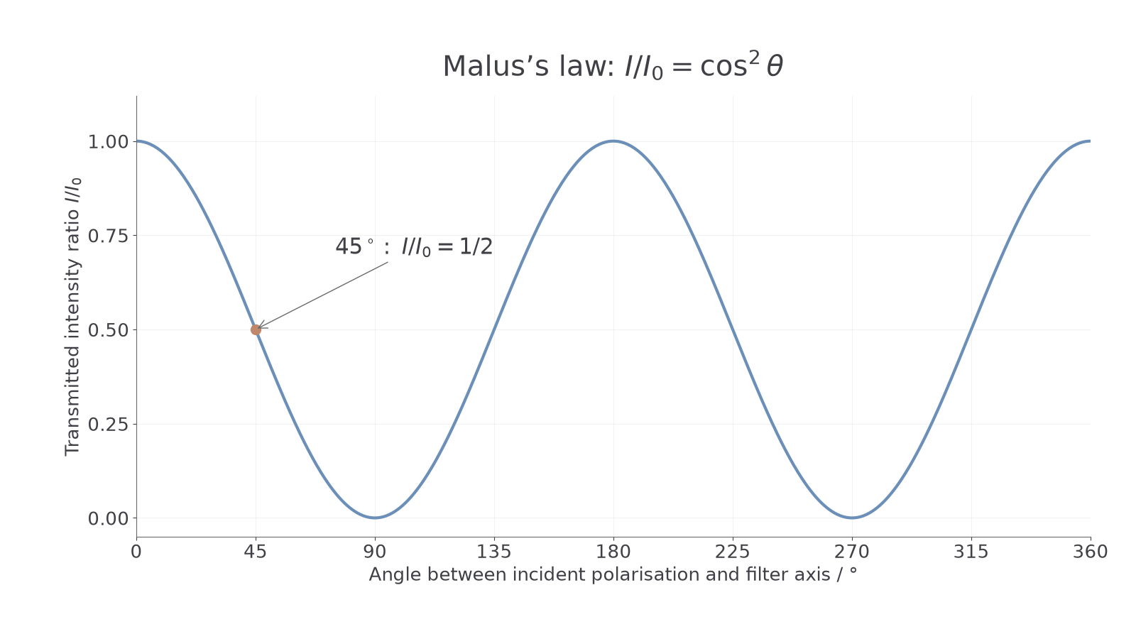
At , the directions align and . At , the directions are crossed and . At , , so half the incident plane-polarised intensity is transmitted. Rotating an axis through returns the same physical orientation; the intensity pattern repeats every .
[DIAGRAM: asset_name: Malus-law intensity curve; asset_slug: malus-law-curve; caption: Relative angle, rather than a filter's absolute orientation, determines transmission; description: A graph of transmitted intensity divided by incident intensity against relative angle from 0 to 360 degrees follows cosine squared. Maxima of one occur at 0,180 and360 degrees; zeros occur at90 and270 degrees; the45-degree point is marked at one half.]
Worked example 1: intensity at a stated angle
Question. Plane-polarised light of intensity meets an ideal filter whose axis is from the incident polarisation direction. Calculate the transmitted intensity.
Plan. Square the cosine before multiplying by intensity.
Answer. .
Check. The intensity lies between zero and the incident value. Using without squaring would give the amplitude factor instead.
For an unknown angle, take the square root of the intensity ratio before using the inverse cosine. If and , then , so . Specify the angle range when choosing a unique solution: different axis rotations can give the same squared cosine.
A graph's angle may be measured from the filter's initial orientation instead. If it begins crossed, transmitted intensity starts at zero and reaches a maximum after a turn. Do not copy a cosine-squared curve starting at maximum unless the angle is measured from initial alignment.
Continue this lesson.
You’re previewing NovaLearn without an account. Create a free account to read the rest.
Create free account