19.3 - Capacitor discharge and the time constant
Explain why capacitor charge, p.d. and discharge current decay exponentially through a resistor. Interpret their graph signs, use the time constant, and determine times or capacitance from voltage data while keeping stored energy distinct from remaining charge.
Charge, p.d. and current during discharge
Can a capacitor be half discharged in charge while only a quarter of its initial energy remains? Yes: charge and p.d. fall together, but energy depends on the square of the p.d. First follow the current through a real discharge path.
An initially charged capacitor is disconnected from its supply and connected across a resistor. Conventional current flows through the resistor from the capacitor's initially positive plate towards its initially negative plate. Electrons redistribute in the opposite direction. Charge does not conduct across the ideal insulating gap between the plates.
[DIAGRAM: asset_name: A resistor discharge circuit; asset_slug: capacitor-discharge-circuit; caption: After the supply is disconnected, a closed resistor loop redistributes the separated plate charge; description: A charged capacitor and resistor form a complete loop with a closed switch. The initially positive and negative capacitor plates are labelled. Conventional discharge current leaves the positive plate through the resistor and returns to the negative plate. The voltage reference is positive on the initially positive plate and the supply is absent.]
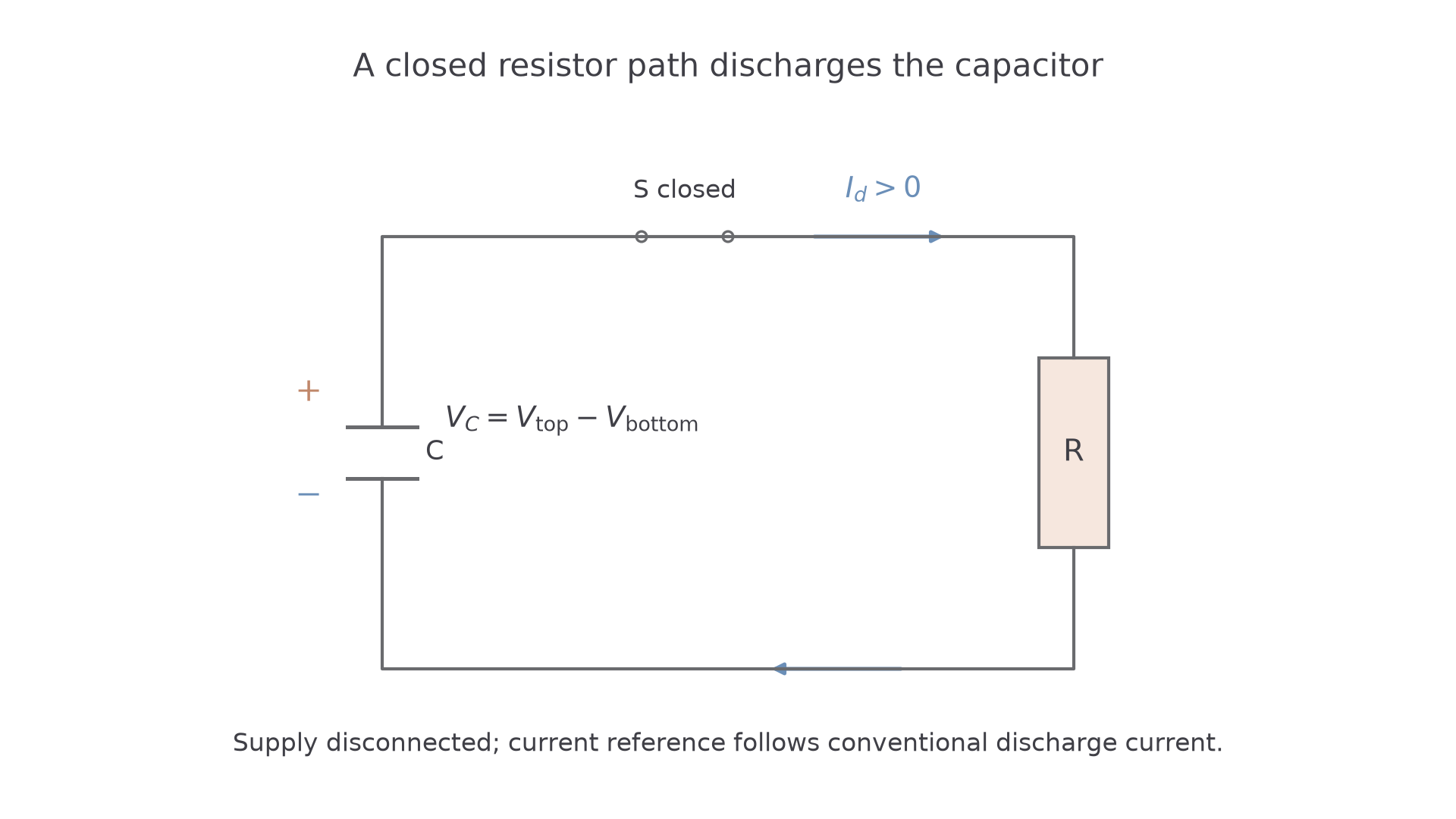
Let be charge on the originally positive plate, and its potential relative to the originally negative plate. During this ordinary discharge they remain positive but decrease. Since , smaller charge gives smaller p.d. The resistor current has magnitude , so it too decreases. As less current flows, less charge leaves in each second. That slowing loss explains the curved decay rather than a straight line to zero.
Here is in , in , resistance in , and current in . These are the capacitance definition and Ohm's law applied to the named components, not new supplied data-sheet relationships.
A current sign needs a stated reference. With discharge current defined from positive plate through the resistor, . If the positive reference were instead the charging direction into that plate, the same discharge would have . A negative current graph then approaches zero from below; it does not mean the physical current reverses halfway through the discharge.
[DIAGRAM: asset_name: Four consistent discharge graphs; asset_slug: capacitor-discharge-graphs; caption: Charge and p.d. fall together, while current sign depends on its reference direction; description: Four graphs show p.d., positive-plate charge, discharge-direction current and charging-direction current against time. The model uses initial p.d. 6 volts, capacitance 100 microfarads, resistance 100 kilohms and time constant 10 seconds. The first three quantities decay positively, while charging-reference current starts negative and approaches zero from below.]
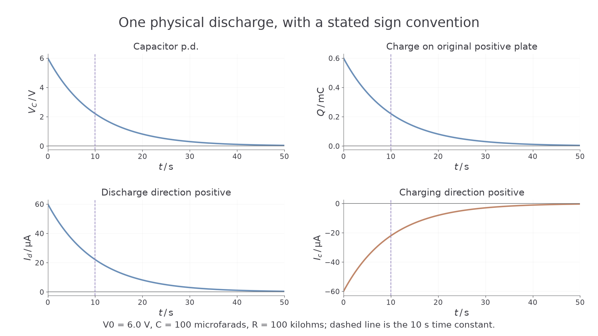
The area under a discharge-direction current–time graph gives charge that has left the original positive plate. Over a complete ideal discharge its total is the initial plate-charge magnitude. Under the opposite current convention, the signed area is negative. The p.d.–time area is not stored energy.
Watch out
State which quantity and reference a graph shows. “Current decreases” is ambiguous for a negative current approaching zero: its magnitude decreases, while its signed value increases towards zero.
The time constant sets the decay timescale
An exponential discharge loses the same fraction of its remaining charge in equal time intervals, rather than the same number of coulombs. The time constant is a convenient interval over which the remaining charge, p.d. or current magnitude falls to about 37 per cent of its starting value.
Time constant
The discharge time constant is the time for charge, p.d. or current magnitude to fall to , approximately 0.368, of its initial value in an ideal resistor–capacitor discharge.
Here the exponential base is Euler's number, not the elementary charge. The remaining fraction is ; the fraction lost in that interval is , approximately 0.632.
RC time constant
Here is time constant in , resistance in , and capacitance in . The resistance is that of the actual discharge path. Resistance and capacitance are constant, and significant leakage or a measuring instrument's extra current path must be included if present.
Not on the data sheet: learn it.
The units make sense: . Increasing resistance reduces current at a given p.d.; increasing capacitance gives more charge at that p.d. Either makes discharge slower.
Worked example 1: calculating the timescale
Question. A capacitor discharges through . Calculate its time constant.
Answer. About , with unrounded value .
Check. After that interval, p.d. is about 0.368 of its starting value, rather than zero or one half. Multiplying the numerical values without their kilo/micro factors would give the wrong timescale.
Continue this lesson.
You’re previewing NovaLearn without an account. Create a free account to read the rest.
Create free account