10.1 - Internal resistance and terminal voltage
Learn why a real source's terminal p.d. can fall when it supplies more current. Use an ideal-source-plus-internal-resistance model, solve complete source–load circuits, and determine e.m.f. and internal resistance from measured voltage–current data.
Energy transferred inside a source
Why might a cell read with no lamp connected but only while lighting the lamp? A cell can supply energy and transfer some energy internally at the same time. The p.d. available to the external circuit is then smaller than its e.m.f.
Model a real source as an ideal source of e.m.f. in series with an internal resistance . The resistor is a model for internal energy transfer; it need not be a separate physical resistor hidden inside the cell. Current passes through both the source and its internal resistance.
[DIAGRAM: asset_name: A real source and its load; asset_slug: circuits-internal-source-model; caption: Internal and external resistances are in the same current path; description: A complete circuit contains an ideal cell of e.m.f. E and internal resistor r inside a dashed source boundary, connected to external load R. Terminal dots A and B bound the entire real source. Labels distinguish the internal p.d. Ir from the terminal p.d. V across the load.]
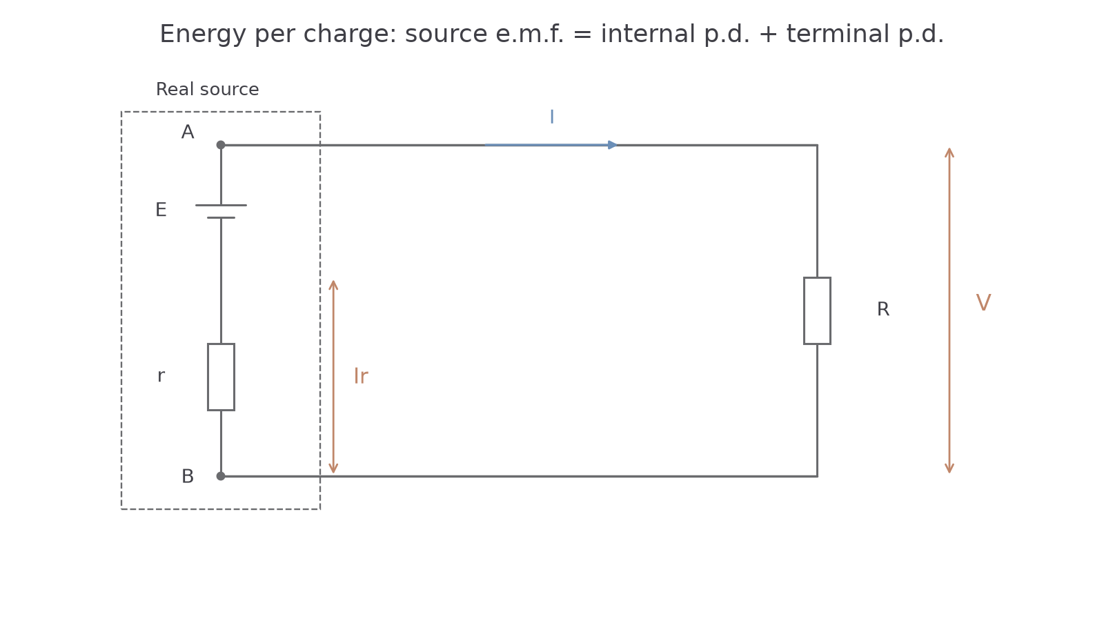
For a charge , the source supplies energy . Some is transferred internally and the rest is delivered to the external circuit. The source's terminal p.d. describes only the external energy per charge. “Lost volts” is shorthand for an internal p.d.; it does not mean that energy or charge has vanished.
A source supplying through of internal resistance has an internal p.d. of . For every coulomb, is supplied, is transferred internally and reaches the external circuit. That accounts for the two readings in the opening question without using up current.
Model limit
Treat and as constant only over the conditions considered. A real cell's temperature, state of charge and operating current can change its behaviour. The simple series-resistance model is an approximation, not a complete description of its chemistry.
The energy account also gives power: the source supplies , the external circuit receives and the internal resistance transfers , all in watts when SI units are used. The power relation was taught earlier and is not on the data sheet: learn it. A hot or depleted source may therefore behave differently during a long experiment.
Terminal p.d. and the complete resistance
Conservation of energy per charge connects the three voltages: the e.m.f. supplies the internal p.d. plus the external terminal p.d. Current therefore affects the external voltage even if the e.m.f. remains unchanged.
A discharging source
E.m.f. and terminal p.d. are in volts, current in amperes and internal resistance in ohms. These signs describe a source delivering current to an external load. A charging source needs its actual current direction considered separately.
Not on the data sheet: learn it.
If the load is a resistor , its p.d. is . Substitution gives , hence . This is a derived complete-circuit relation, not a separate printed data-sheet formula. Include internal resistance when calculating current; use only the external resistance to find the p.d. delivered to the load.
Worked example 1: find current before terminal voltage
Question. A source has e.m.f. and internal resistance . It supplies a resistor. Calculate the current and terminal p.d.
Check. The internal p.d. is , and . Terminal p.d. is smaller than e.m.f. while current flows from the source.
You can work backwards from a load measurement too.
Exam-style example: deducing internal resistance
Question. A source of e.m.f. supplies a load. Its terminal p.d. is . Determine the source's internal resistance.
Plan. The load p.d. gives current. The missing p.d. then gives internal resistance.
Check. The complete resistance is , giving , consistent with the measured terminal p.d.
Continue this lesson.
You’re previewing NovaLearn without an account. Create a free account to read the rest.
Create free account