20.5 - Magnetic flux and flux linkage
Calculate magnetic flux through an area and distinguish it from the flux linkage of a multi-turn coil. Use projected area and a clearly defined angle to track how rotating a coil changes signed linkage, even when magnetic flux density stays constant.
Field through a perpendicular area
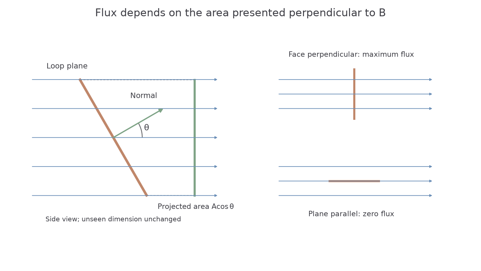
A loop rotates in a constant magnetic field. How can the flux through it change when the field itself does not? Flux depends on both the field and the area presented perpendicular to it. Turning the loop changes that projected area.
Magnetic flux density describes the magnetic field at a position. Magnetic flux describes the field passing through a chosen area. It is a different quantity: a larger loop can enclose more flux in exactly the same uniform field.
Magnetic flux
Magnetic flux is the product of magnetic flux density and the cross-sectional area perpendicular to the direction of the magnetic flux density.
This “through an area” picture is a way of using the field model. It does not mean magnetic material flows through the loop. Field lines can help you picture orientation, but flux is not a literal count of drawn lines.
Flux through a perpendicular area
is magnetic flux in webers, uniform magnetic flux density in teslas and area perpendicular to the field in square metres. If the field is oblique to a surface, use its perpendicular projected area rather than the full surface area.
Not on the data sheet: learn it.
One weber is one tesla square metre:
Doubling or the perpendicular area doubles the flux. The simple product assumes a uniform field across that area. If part of a loop lies outside the field region, count only the area through which this field passes; do not multiply by the loop's whole area automatically.
[DIAGRAM: asset_name: Perpendicular area and magnetic flux; asset_slug: flux-projected-area; caption: Rotating a loop changes its perpendicular projected area; description: A side-view construction shows a tilted planar loop with area A in a uniform rightward field. Its normal makes angle theta to the field and a projected area perpendicular to the field is labelled A cosine theta. A comparison panel shows the loop face perpendicular to the field for maximum flux and edge-on for zero flux.]
Worked example 1: an area conversion
Question. A uniform field of is perpendicular to an area of . Determine the magnetic flux.
Plan. Square the centimetre conversion before multiplying by field strength.
Answer. .
Check. The area is much less than one square metre, so the flux is much less than .
For a circular single-turn loop, use its enclosed area , not the wire's cross-sectional area. A loop of radius perpendicular to has
The area is what the loop encloses, not how much conducting material it contains.
Adding the linkage of many turns
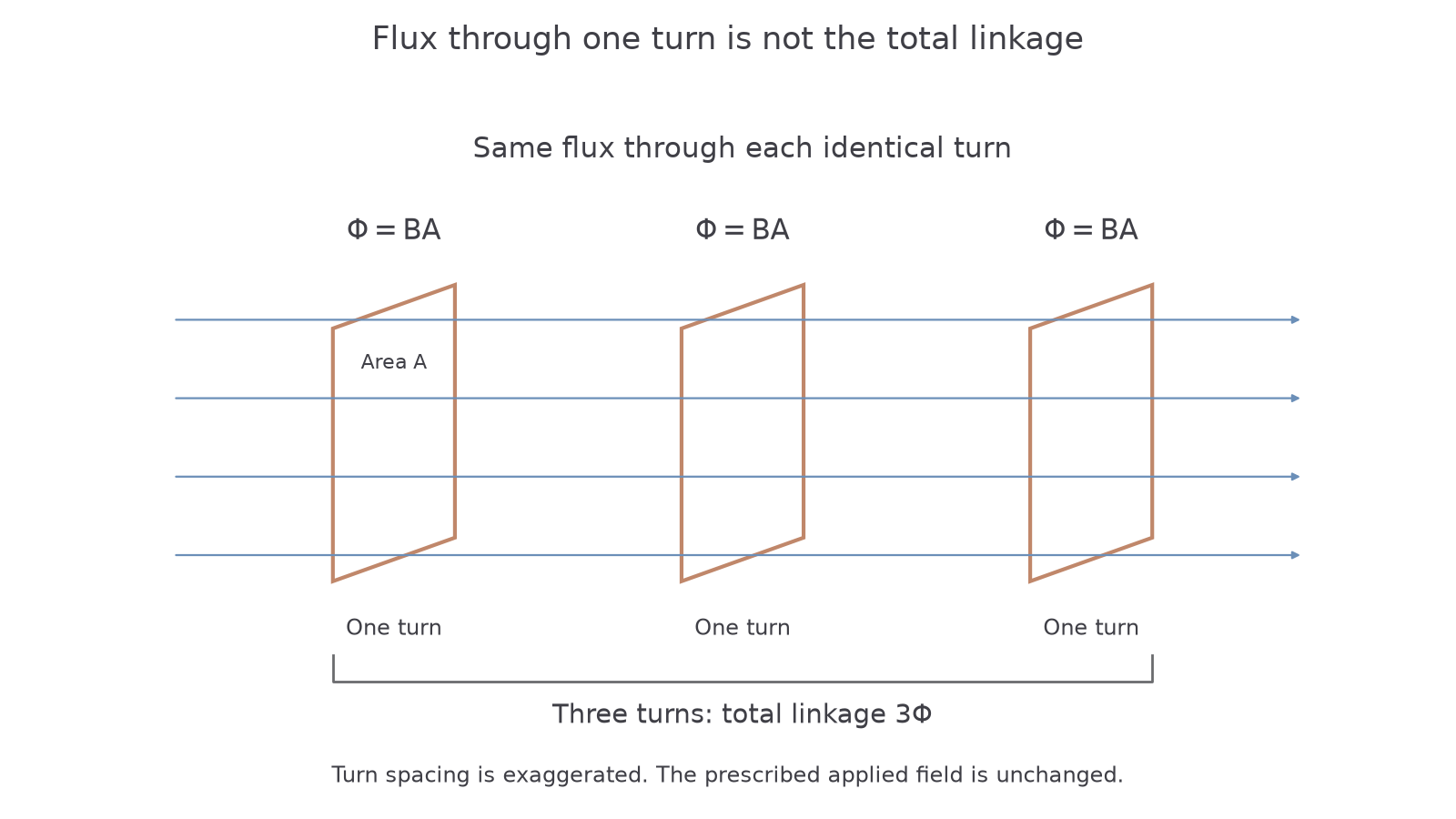
A coil may have many turns, each enclosing the same magnetic flux. Its flux linkage adds the flux through all those turns. Adding turns increases linkage without necessarily changing the magnetic field or the flux through any one turn.
For turns, each linked by flux , the flux linkage is . Think of a ten-turn coil in a prescribed uniform field: each turn encloses its own copy of the same area. The field itself has not become ten times stronger merely because we count ten linked turns.
Flux linkage
is the dimensionless number of turns, the flux through one turn in webers, uniform flux density in teslas and the area of each turn perpendicular to the field. This form assumes all turns link the same flux. Flux linkage is expressed in webers; “weber-turns” also makes the turn count explicit.
Not on the data sheet: learn it.
If the turns enclose different areas or experience different fields, their fluxes need not be equal. Then add the individual linkages rather than multiplying one unrepresentative flux by . For the small, closely wound coils in our calculations, the equal-flux approximation will be stated or evident from a uniform-field model.
[DIAGRAM: asset_name: Flux through a turn and linkage of a coil; asset_slug: flux-and-linkage; caption: Each turn has flux Phi while the complete coil has linkage N Phi; description: Three separated copies of identical rectangular turns are shown in the same uniform field, with one turn's enclosed area marked A. Each is labelled flux Phi equals BA. A brace identifies three turns and total linkage three Phi; a note states that spacing is exaggerated and the applied field is unchanged.]
Worked example 2: the turn count matters
Question. Each turn of a 200-turn coil encloses flux . Calculate the coil's flux linkage.
Plan. Multiply the flux per turn by the number of turns.
Answer. .
Check. Dividing the linkage by 200 recovers the original flux through one turn.
Continue this lesson.
You’re previewing NovaLearn without an account. Create a free account to read the rest.
Create free account