21.2 - Half-wave and bridge rectification
Learn how diodes turn an alternating supply into a unidirectional output. Trace the complete current paths through a bridge rectifier and sketch half-wave and full-wave outputs on the same time scale as their input.
Passing one half of the input
Can a circuit make current pass through a load in the same direction during both halves of an alternating supply? A diode gives us the first step: it allows current in one direction and blocks it in the other. One diode alone discards alternate half-cycles. Four carefully connected diodes can make use of both.
Rectification converts an alternating current or voltage into a unidirectional current or voltage. Unidirectional does not mean constant: a rectified supply can rise and fall while retaining the same polarity across its load.
An ideal diode conducts with zero voltage across it when forward biased and allows no current when reverse biased. In the standard symbol, conventional current can pass from the triangle towards the bar, from anode to cathode. The circuit below puts one diode in series with a load resistor. The output is measured across the load, with its upper terminal taken as positive.
[DIAGRAM: asset_name: A single-diode half-wave rectifier; asset_slug: ac-half-wave-circuit; caption: The diode completes the load circuit for one source polarity and blocks it for the other; description: A complete low-voltage alternating-source circuit contains one series diode oriented towards the upper end of a load resistor. The source terminals are A above and B below. When A is positive relative to B, arrows show current from A through the diode, down the load and back to B. The diode cathode bar and the positive output reference are labelled.]
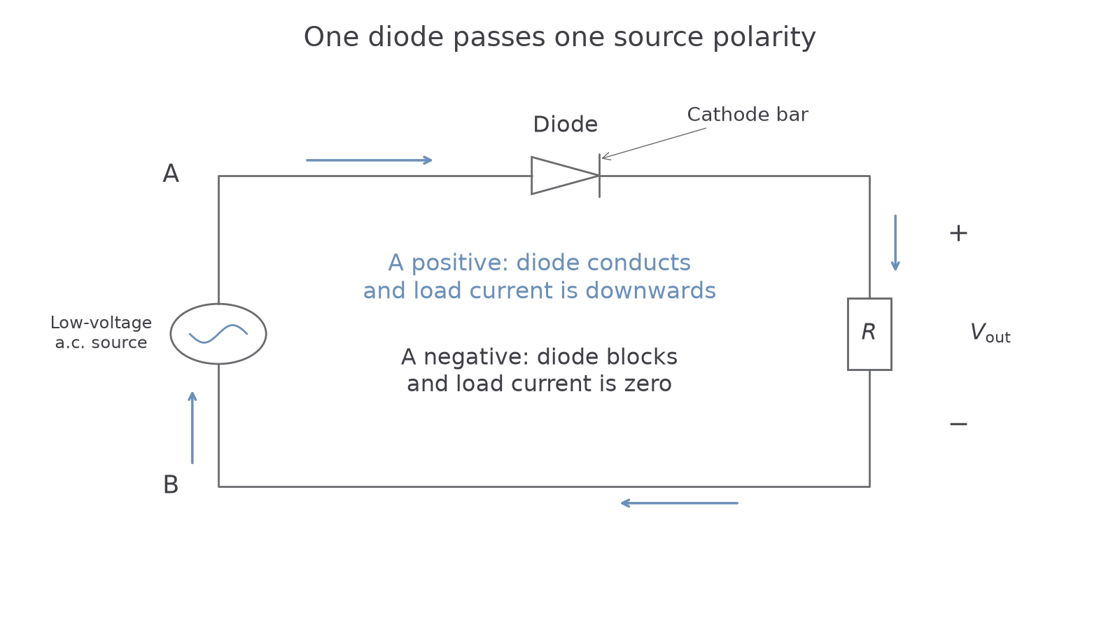
When source terminal A is positive relative to B, this diode is forward biased. Current passes through the diode, down the resistor and back through the source. With an ideal diode, the output voltage equals the input during this half-cycle. When A becomes negative relative to B, the diode is reverse biased. The circuit is open, current is zero and the voltage across the resistor is zero. The negative input half-cycle is blocked, rather than turned upside down.
For example, a sinusoidal input with peak and frequency has period . If it starts at zero and rises positively, the half-wave output follows the positive input from to , is zero from to , then repeats. Its peaks are still apart: half-wave rectification does not double the repetition frequency.
Model limit
An ideal conducting diode has no voltage drop. A real diode needs a forward voltage and dissipates some energy. Use any forward-voltage value given in a question; do not subtract an assumed value when none is specified. The diode must also be used within its current and reverse-voltage ratings.
Using both halves with a bridge
A bridge sends either source polarity through the load in the same direction. The trick is to provide two possible conducting paths, each using a different pair of diodes. You can determine them from the diode directions without memorising a picture.
Call the a.c. input terminals A and B, the positive output terminal P and the negative output terminal N. In the bridge shown, the allowed conventional-current directions are D1: A to P, D2: B to P, D3: N to B and D4: N to A. The resistor connects P to N.
[DIAGRAM: asset_name: The two conducting paths through a bridge; asset_slug: ac-bridge-paths; caption: Different diode pairs conduct on alternate half-cycles while current always passes from P to N through the load; description: Two complete bridge-rectifier circuits share labels A and B for the alternating input, P above and N below for the output. Four diodes permit A to P, B to P, N to B and N to A. One panel highlights the complete loop A through D1 to P, down the resistor to N, through D3 to B and through the source back to A. The other highlights B through D2 to P, down the resistor to N, through D4 to A and through the source back to B. Non-conducting branches are grey.]
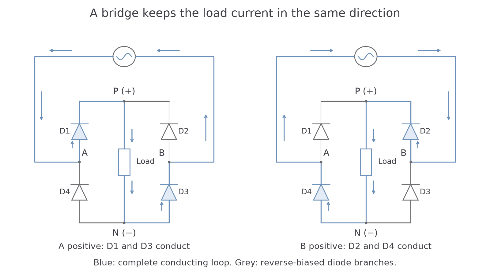
When A is positive relative to B, conventional current follows
and the source completes the loop back to A. D1 and D3 conduct; D2 and D4 are reverse biased.
When B is positive relative to A, current follows
and returns through the source to B. Now D2 and D4 conduct. In both cases, the current through the load is from P to N. Input current reverses, but load current does not.
Continue this lesson.
You’re previewing NovaLearn without an account. Create a free account to read the rest.
Create free account