21.2 - Smoothing a rectified supply
Learn how a capacitor reduces the variation in rectified voltage. Explain the charging and discharging paths, compare the effects of capacitance and load resistance, and use a discharge trace to test the circuit model.
Keeping the load supplied between peaks
A bridge rectifier's output falls to zero between pulses, so how can a capacitor keep its load powered during those gaps? A charged capacitor can transfer stored energy to the load while the source voltage is too low to drive current into it. The output then falls gradually instead of following every pulse down to zero.
Connect the capacitor in parallel with the load, across the rectifier's output terminals. It has the same voltage as the load. The diagram uses a single-diode rectifier to make the charging and discharging routes easy to see; a capacitor works across a bridge's output in the same way.
[DIAGRAM: asset_name: A smoothing capacitor across the load; asset_slug: ac-smoothing-circuit; caption: The diode charges the parallel capacitor near a supply peak and the capacitor then drives current through the load; description: A complete low-voltage half-wave circuit has an alternating source, a forward diode in the upper wire, and parallel capacitor and resistor branches between the positive output rail and the return rail. The capacitor's upper plate is positive. A charging arrow passes through the diode, while separate arrows show the diode-off discharge loop from the positive capacitor plate through the load to the negative plate. The capacitor is not in series with the resistor.]
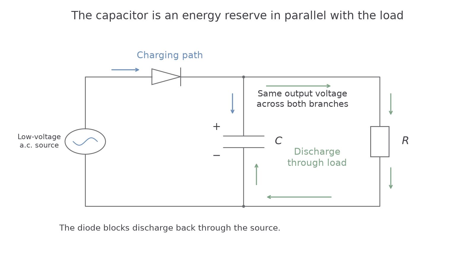
As the rectified source voltage rises above the capacitor voltage, a diode path conducts and the capacitor charges towards the peak. After the peak, the source voltage falls below the capacitor voltage. The diode path becomes reverse biased, preventing discharge back through the source. The capacitor now discharges through the resistor. Its positive output terminal remains positive and current continues through the load in the same direction as before.
At a later rising pulse, the source voltage catches up with the falling capacitor voltage and recharging begins. It begins when the two voltages meet, not automatically at the next zero crossing or at a fixed fraction of the cycle. With real diodes, the source must exceed the capacitor voltage by the necessary forward voltage drop as well.
Ripple voltage
The peak-to-peak ripple voltage is the difference between the maximum and minimum output voltages in a repeating cycle. Here , with all voltages in volts. A smaller ripple gives a steadier output.
For example, a smoothed output varying from down to has ripple . This is not its maximum voltage or its mean voltage. A capacitor reduces ripple; it does not normally remove it completely or hold the output independent of the load.
Watch out
The capacitor supplies energy and charge during discharge; it does not make current disappear from the circuit. In the closed capacitor–load loop, the same conventional current enters and leaves the resistor. A series capacitor would not provide the parallel energy reserve shown here.
Why larger capacitance reduces ripple
At a given voltage, a larger capacitance stores more charge. Removing a given amount of charge therefore causes a smaller fall in voltage. For the same rectifier, input frequency and load resistance, increasing capacitance keeps the output closer to its peak between charging pulses.
You already know the charge relation : charge in coulombs equals capacitance in farads times voltage in volts. It is not on the data sheet. It explains the trend without a special ripple formula: a larger needs a greater charge loss for the same voltage decrease.
During a diode-off interval, the capacitor discharges through the load resistance just as in the earlier discharge experiment. If its voltage is at the start of that interval, the model is
Discharge between charging pulses
Here and are voltages in volts, is time since the start of the discharge interval in seconds, is load resistance in ohms and is capacitance in farads. The time constant is , in seconds. This model assumes a constant resistive load, negligible leakage and no charging current during the interval.
On the data sheet for Paper 4.
The relation for the time constant must be recalled; it is not separately on the data sheet. Increasing increases the time constant, so voltage falls more slowly. Do not apply one exponential to an entire repeating waveform: the capacitor is being recharged during part of every cycle.
Continue this lesson.
You’re previewing NovaLearn without an account. Create a free account to read the rest.
Create free account