10.3 - Potentiometers and null methods
Learn how a uniform resistance wire provides a known p.d. per unit length, how a galvanometer detects a balance without drawing current from a test cell, and how balance lengths compare e.m.f.s or potential differences. Distinguish zero detector current from zero current in the working circuit.
A uniform wire as a voltage scale
How can a meter reading of zero help you measure a non-zero e.m.f.? A null method compares two effects until they balance. A potentiometer uses an adjustable p.d. along a wire to balance the e.m.f. or p.d. being measured, and a sensitive current detector tells you when the balance is reached.
First create the voltage scale. Connect a long uniform resistance wire AB into a complete circuit with a driver supply and a variable resistor. Conventional current flows along the wire from its higher-potential end A towards B. For a uniform material and cross-sectional area at constant temperature, resistance is proportional to length. The p.d. is therefore proportional to length when the current is the same throughout the wire.
[DIAGRAM: asset_name: A uniform potential gradient; asset_slug: circuits-potentiometer-wire; caption: A uniform wire with steady current has a constant p.d. per unit length; description: A complete driver circuit contains a cell, variable resistor and straight resistance wire AB. The positive driver terminal connects towards A. A movable contact J divides the wire at length l from A along a total length L. A label VAB marks the whole-wire p.d.; no test branch is yet connected.]
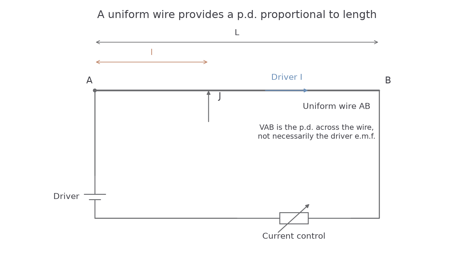
Potential gradient
Potential gradient is in , whole-wire p.d. in volts, wire length in metres and distance from A to contact J in metres. is the p.d. between A and J. Use a uniform wire, steady current and negligible current drawn by an output branch.
Not on the data sheet: learn it.
These relations follow from and : for fixed resistivity , cross-sectional area and current , is proportional to . Here the material's cross-sectional area is a different use of the letter from the endpoint label A; context distinguishes them.
Worked example 1: a voltage selected by length
Question. A uniform wire has p.d. across its ends. Determine the p.d. between its high-potential end and a contact along the wire, with negligible output current.
Check. The contact spans 35% of the wire, so its p.d. is 35% of the whole-wire p.d.
The driver supply e.m.f. need not equal , because the variable resistor and any source internal resistance also have p.d.s. Changing the variable resistor changes wire current and potential gradient. For a valid comparison, leave that setting and the wire's temperature steady between balance readings.
Galvanometer balance and no loading
A galvanometer detects a small current and its direction. Connect the positive terminal of a test cell to end A, and its negative terminal through the galvanometer to contact J. The test-cell e.m.f. then opposes the p.d. from A to J around this comparison loop.
[DIAGRAM: asset_name: A complete potentiometer null circuit; asset_slug: circuits-potentiometer-null; caption: At balance, the detector branch draws no current from the test cell, while the driver current continues; description: A complete driver circuit supplies uniform wire AB through a variable resistor. A separate branch connects A to the positive terminal of the test cell, then from its negative terminal through a galvanometer to the movable contact J on AB. The wire A-to-J segment and test cell therefore oppose in the comparison loop. A length marker l runs from A to J.]
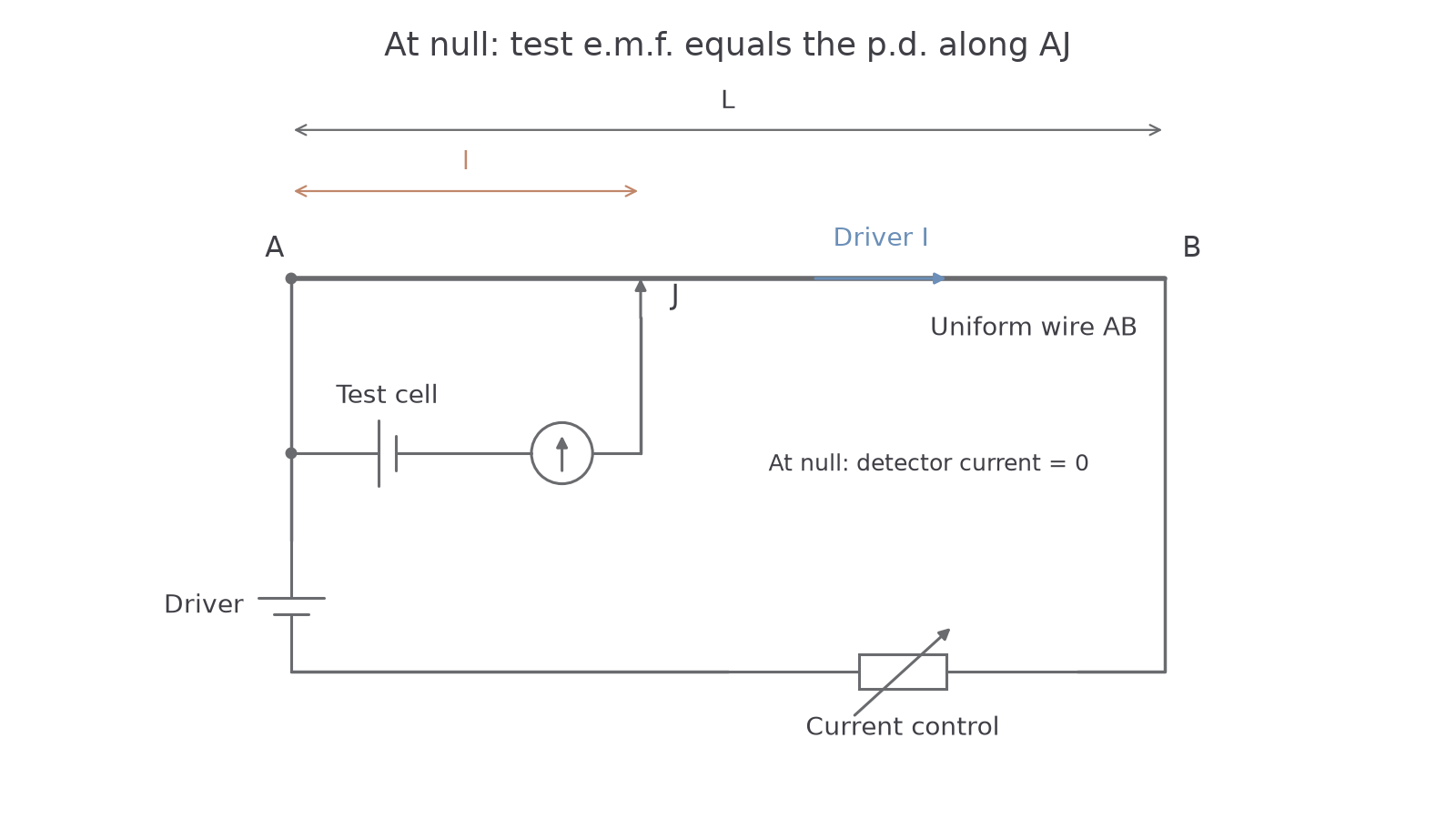
Move J along the wire until the galvanometer reads zero. On opposite sides of the balance position it should deflect in opposite directions. That check distinguishes a genuine balance from a broken connection that merely leaves the detector at zero everywhere.
At the null point, no current flows through the test-cell/galvanometer branch. The test cell has no internal-resistance p.d. , so its terminal p.d. equals its e.m.f. The opposing wire segment p.d. therefore equals that e.m.f.:
Here is in volts, in and balance length in metres. This null relation is not on the data sheet: learn it. The driver current through the resistance wire is still non-zero; otherwise there would be no useful wire p.d. to make the comparison.
Continue this lesson.
You’re previewing NovaLearn without an account. Create a free account to read the rest.
Create free account