DC4, DC7 - Multiple sources and restricted nodes
Real networks may collect material from several places and deliver it to several destinations. DC4 combines those entrances and exits using a supersource and supersink. DC7 refines the model to respect a shared processing limit at a node and explains which contextual restrictions a static flow network can represent.
Supersource and supersink capacities
Two depots can supply 9 parcels per minute, but their shared packing station can handle only 6. How can a network represent both the separate supplies and the shared limit? First we combine several suppliers and destinations into a single-source, single-sink model; the station limit will then need its own constraint.
A supersource is an added node with an arc directed from to each original source. A supersink has an arc directed from each original sink to . The original sources and sinks now obey conservation, because supply and receipt pass through the new arcs.
The added nodes are bookkeeping devices. They do not build new routes between the original nodes or increase the original network's possible throughput, provided their capacities faithfully represent the original supplies and receipts.
Choosing added capacities
If an original source has a supply limit , its supersource arc has capacity ; if a sink has a receipt limit , its supersink arc has capacity . If no external limit is given, a safe finite capacity is the sum of outgoing upper capacities at an original source, or the sum of incoming upper capacities at an original sink. Here original sources have no incoming arcs and original sinks have no outgoing arcs; lower bounds are zero.
Why are those finite sums safe? A source cannot send more than all its outgoing arcs can carry, and a sink cannot receive more than all its incoming arcs can carry. Using these sums adds no restriction. A larger finite value also works. An arbitrarily small value may create an artificial bottleneck; writing “infinity” is unnecessary when a finite bound is available.
Worked example 1: preserving stated supply limits
Question. The only original arcs are of capacity 8, of capacity 6, of capacity 7 and of capacity 9. Depot can supply at most 5 units per minute and at most 4. Destinations can receive at most 6 and 8 respectively. Add a supersource and supersink with suitable capacities.
Plan. Connect the sources and sinks in the correct directions, using their stated external limits.
Answer. Add these four directed arcs with capacities 5, 4, 6 and 8. This part of the model limits total supply to .
Check. A flow of 5 from and 4 from , with 6 sent to and 3 to , meets all the original and added arc capacities. The construction has not unnecessarily reduced the available supply.
Keep the original pipes but remove only the external supply and receipt limits. Now choose finite capacities which cannot restrict the original network.
Worked example 2: using incident capacity sums
Question. For the same four original arcs, no separate supply or receipt limits are given. Find safe finite capacities for the added arcs.
Plan. Sum outgoing capacities at each source and incoming capacities at each sink.
Answer. Capacities 8, 6, 7 and 9 respectively are safe; larger finite capacities would also be suitable.
Check. Any original feasible flow satisfies , , , . Assigning these same amounts to the added arcs extends it to the new network, so no original feasible delivery is lost.
In a diagram, source and sink positions can be misleading. Trace the arrows before adding arcs; a leftmost node with incoming flow is not automatically an original source.
Watch out
Wrong: “The current flow from a source is 3, so its new arc should have capacity 3.” That may block later augmentation. Use its actual supply limit, or a safe upper bound from outgoing capacities, and include the direction arrow.
Build a fresh construction from the complete arc list.
Splitting a restricted-capacity node
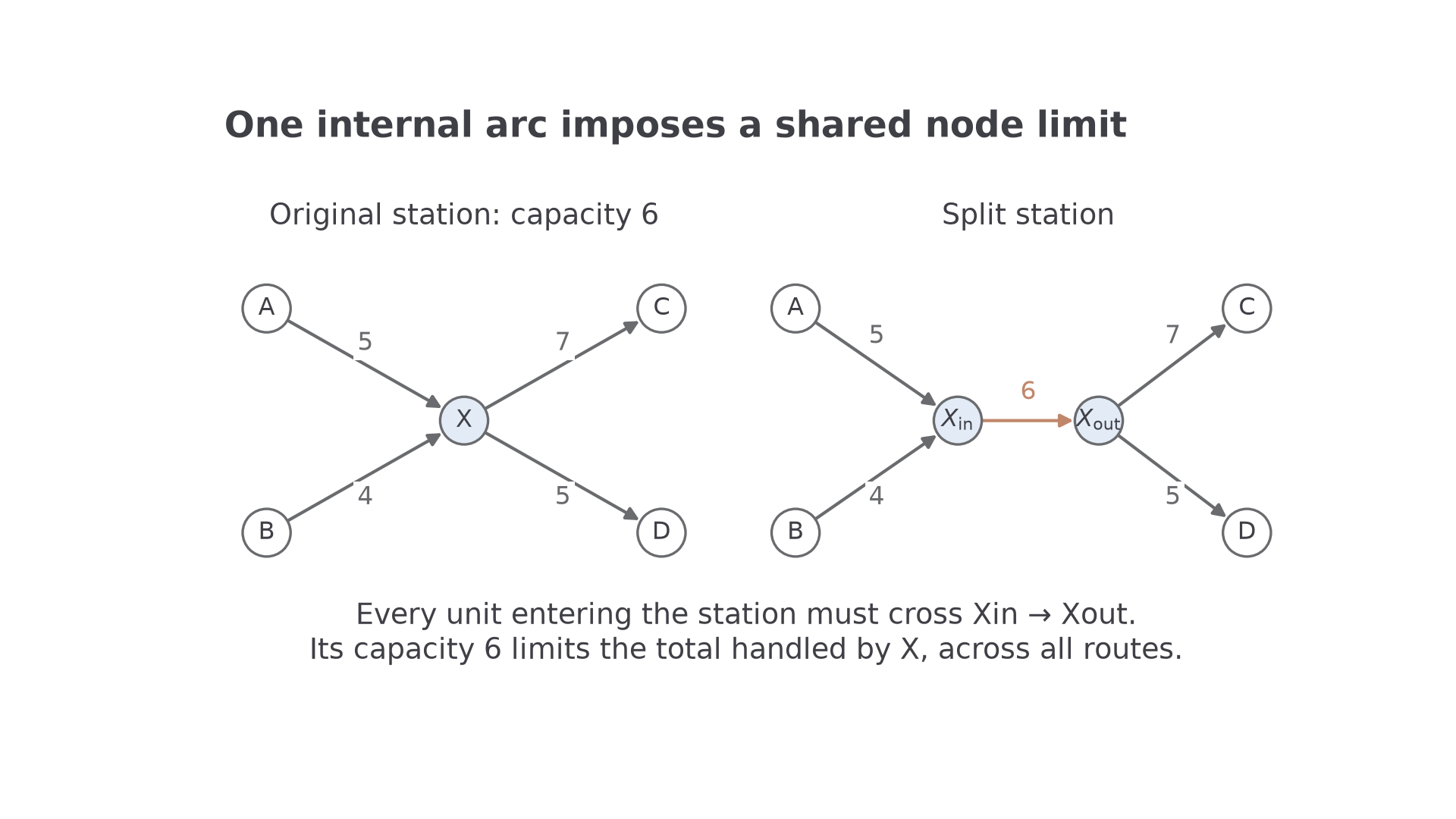
An arc capacity limits one route. A node capacity limits the total passing through a shared facility, however that flow is divided between routes. Several incoming arcs each with capacity 6 would not, by themselves, limit the facility's total to 6.
Node splitting
Replace a node of restricted capacity by and . Redirect every original incoming arc to , and every original outgoing arc from , preserving their capacities. Add with capacity . All flow through the facility must cross this internal arc.
Conservation at both new nodes makes total incoming flow equal the internal-arc flow and total outgoing flow. Thus one arc enforces the shared limit exactly. Do not leave a bypass from an incoming route to , because it would evade the restriction. If the facility is itself a supplier or destination, route its relevant supersource or supersink connection through the limiting arc too, according to what the stated processing limit includes.
[DIAGRAM: asset_name: Splitting a station with restricted capacity; asset_slug: aqa7367-node-splitting; caption: An internal arc of capacity 6 limits the station's combined throughput; description: The left panel shows A to X capacity 5, B to X capacity 4, X to C capacity 7 and X to D capacity 5, with X having a shared limit 6. The right panel redirects A and B into X in, connects X in to X out with a clay arc of capacity 6, and sends outgoing arcs from X out to C and D. All original arc capacities are preserved.]
The following examples use depots as sources and destinations as sinks; any added supernode arcs are assumed large enough to impose no further restriction.
Continue this lesson.
You’re previewing NovaLearn without an account. Create a free account to read the rest.
Create free account