4.7.3.4b - Transformer Power, Current and Transmission
A transformer can change potential difference, but an ideal transformer does not create extra electrical power. This Higher-tier physics-only lesson uses that idea to calculate currents and to explain why the National Grid transmits electricity at high potential differences. The key pattern is simple but powerful: for the same power transfer, a larger potential difference means a smaller current.
Ideal Transformer Power
A real transformer always wastes some energy, usually by heating the coils and core. In the AQA GCSE model for this lesson, we often start with an ideal transformer: a transformer that is 100% efficient.
Ideal Transformer
An ideal transformer is a transformer that is 100% efficient, so its electrical power output equals its electrical power input.
A brief reminder of the mechanism: an alternating current in the primary coil produces a changing magnetic field in the core, and that changing field induces a potential difference across the secondary coil.
If a transformer is 100% efficient, the power in the primary coil is equal to the power in the secondary coil:
Electrical power in a coil is found from potential difference multiplied by current, so:
Ideal Transformer Power Equality
where is the potential difference across the primary coil, is the current in the primary coil, is the potential difference across the secondary coil, and is the current in the secondary coil.
[DIAGRAM: asset_name: ideal_transformer_power_and_current - diagram 1; asset_slug: 112_4_7_3_4b_transformer_power_current_and_transmission_diagram1; file: diagram_assets/112_4_7_3_4b_transformer_power_current_and_transmission_diagram1.png; recommended_method: image_gen; description: Built-in Codex Image Gen transformer schematic showing a primary coil, iron core and secondary coil, with the secondary coil drawn with clearly more turns for a step-up transformer. The example labels show , , , , and equal powers . The visual teaches that stepping up potential difference lowers current for the same ideal power transfer. Generated with built-in Codex Image Gen; nearby prose states the exact relationships for accessibility.]
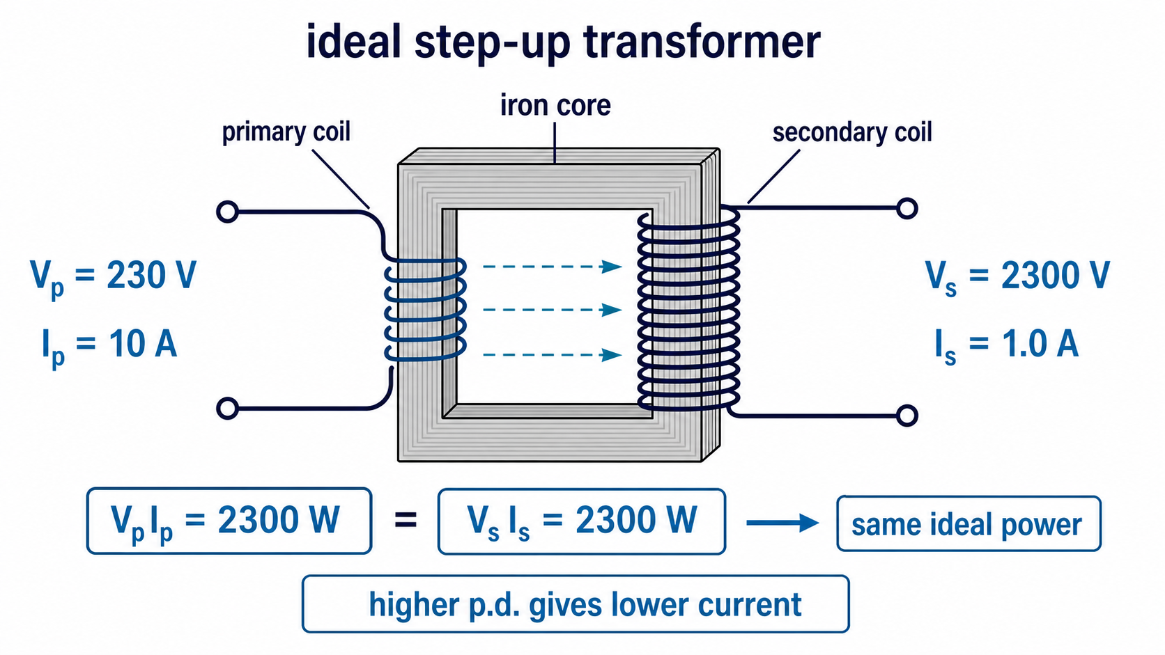
The equation is given on the Physics equation sheet. The exam skill is choosing it, identifying primary and secondary values, rearranging it correctly, and using watts for power.
Current Changes with Potential Difference
The ideal transformer equation shows that current changes in the opposite direction to potential difference when the power transfer is the same.
For a step-up transformer, the secondary potential difference is greater than the primary potential difference. In an ideal transformer, the secondary current must therefore be smaller than the primary current. The transformer has not made extra power; it has transferred roughly the same power at a higher potential difference and a lower current.
For a step-down transformer, the secondary potential difference is smaller than the primary potential difference. In an ideal transformer, the secondary current is therefore larger than the primary current.
This is the common AQA trap: "step-up" describes the potential difference, not the current. A step-up transformer steps up and steps down . A step-down transformer steps down and steps up , assuming ideal power transfer.
Worked example: an ideal transformer has , , and . Calculate the secondary current.
The potential difference has increased by a factor of 4, so the current has decreased by a factor of 4.
Input Current Calculations
AQA specifically expects you to calculate the current drawn from the input supply to provide a particular power output. The phrase "current drawn from the input supply" means , the primary current.
If the output power is given directly, use:
for an ideal transformer, then:
so:
[DIAGRAM: asset_name: input_current_from_output_power - diagram 2; asset_slug: 112_4_7_3_4b_transformer_power_current_and_transmission_diagram2; file: diagram_assets/112_4_7_3_4b_transformer_power_current_and_transmission_diagram2.png; recommended_method: deterministic_drawn; description: Exact deterministic worked-equation flow showing an output device needing , an ideal transformer, an input supply of , and the calculation . The visual teaches how to identify input current from output power without confusing primary and secondary values. Deterministic drawing is required because the values, equation layout and labels are assessed.]
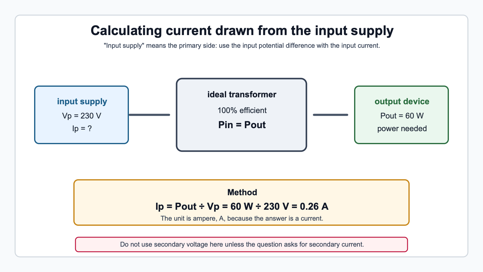
Worked example: an ideal transformer supplies a output device. The input supply is . Calculate the current drawn from the input supply.
The current drawn from the input supply is to 2 significant figures.
If a question gives secondary values instead of output power, calculate output power first:
then use for the ideal transformer.
Continue this lesson.
You’re previewing NovaLearn without an account. Create a free account to read the rest.
Create free account