4.7.3.4a - Transformer Structure and Turns Ratio
Transformers are Physics-only, Higher Tier content in AQA GCSE Physics. A transformer uses two coils on an iron core to change an alternating potential difference. In this lesson, the focus is the structure of a basic transformer and the ratio linking potential differences to the numbers of turns on the coils.
Basic transformer structure
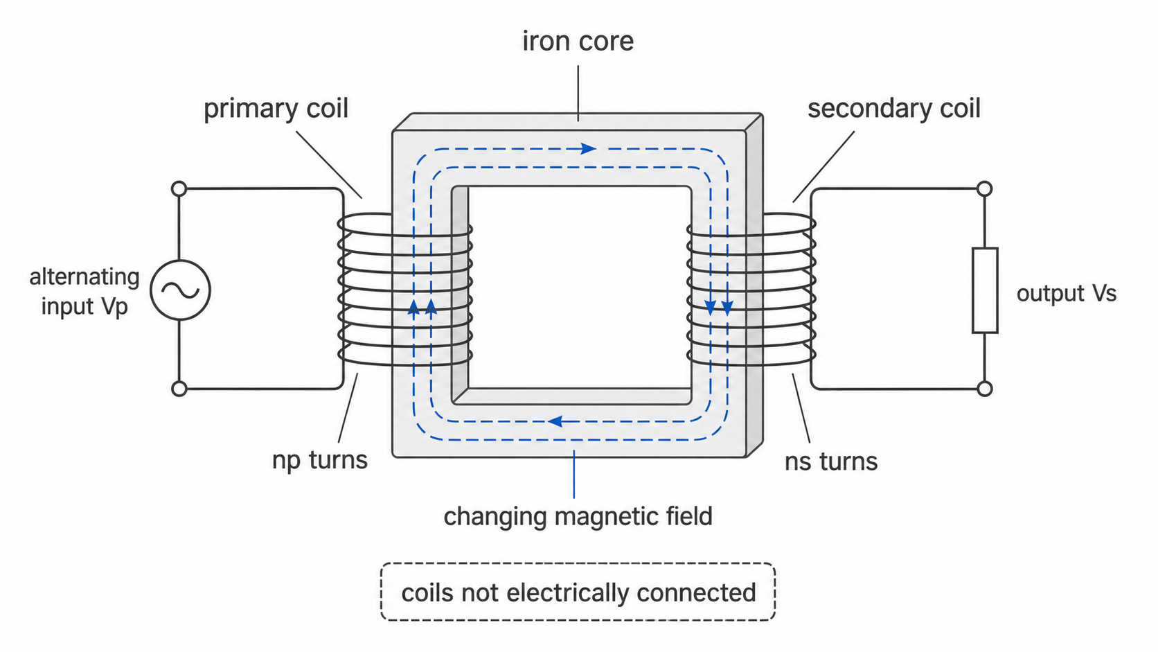
A basic transformer consists of a primary coil and a secondary coil wound on an iron core. The primary coil is connected to the input alternating supply. The secondary coil is connected to the output circuit.
Transformer
A transformer is a device that uses two coils wound on an iron core to change the size of an alternating potential difference.
The coils are separate pieces of wire. They are not electrically connected to each other. The iron core links them magnetically because iron is easily magnetised.
[DIAGRAM: asset_name: basic_transformer_structure; asset_slug: 111_4_7_3_4a_transformer_structure_and_turns_ratio_diagram1; file: diagram_assets/111_4_7_3_4a_transformer_structure_and_turns_ratio_diagram1.png; recommended_method: image_gen; description: Image-generated transformer schematic showing a rectangular iron core, a primary coil on the left connected to an alternating input labelled Vp and np turns, and a secondary coil on the right connected to an output labelled Vs and ns turns. It labels the coils as not electrically connected and shows the changing magnetic field in the core.]
In AQA questions, do not add detail about laminations or eddy currents in the core. The specification says that knowledge of laminations and eddy currents is not required. For this lesson, the important core idea is simpler: iron is used because it is easily magnetised.
How the coils are linked
A transformer works with alternating current in the primary coil. Alternating current keeps changing direction, so the magnetic field produced by the primary coil also keeps changing.
The changing magnetic field passes through the iron core. Because iron is easily magnetised, the core helps link the changing magnetic field from the primary coil to the secondary coil.
The changing magnetic field through the secondary coil induces a potential difference across the secondary coil. If the secondary coil is part of a complete circuit, an alternating current is induced in the secondary circuit.
This is the key transformer sequence:
- alternating current in the primary coil
- changing magnetic field in the iron core
- induced potential difference across the secondary coil
- induced current in the secondary circuit if the circuit is complete
The primary and secondary coils do not need to touch or share a wire. The energy transfer is through the changing magnetic field in the core, not through a direct electrical connection between the coils.
The turns ratio equation
The number of turns on each coil controls the ratio of the potential differences across the coils. A turn is one loop of wire around the core.
Transformer turns ratio
The symbols and units are:
| Quantity | Symbol | Unit |
|---|---|---|
| potential difference across the primary coil | volt, V | |
| potential difference across the secondary coil | volt, V | |
| number of turns on the primary coil | no unit | |
| number of turns on the secondary coil | no unit |
This equation is given on the Physics equation sheet. Higher Tier students need to select it, rearrange it when needed, substitute values correctly, and keep primary quantities together and secondary quantities together.
The same relationship can be written with the secondary values on top:
This version is often useful when you want the secondary potential difference:
Worked example: a transformer has 200 turns on the primary coil and 600 turns on the secondary coil. The potential difference across the primary coil is 12 V. Calculate the potential difference across the secondary coil.
Continue this lesson.
You’re previewing NovaLearn without an account. Create a free account to read the rest.
Create free account