4.7.2.3 - Electric Motors
An electric motor uses the motor effect to make something rotate. In this Higher Tier lesson, the important model is a coil of wire carrying a current in a magnetic field. The forces on the two sides of the coil act in opposite directions, giving a turning effect.
Why a coil turns
A conductor is a material that allows charge to flow. In this lesson, the conductor is the wire in a coil. When current flows through a conductor in a magnetic field, the conductor experiences a force. This is the motor effect.
Motor effect
The motor effect is the force on a current-carrying conductor in a magnetic field.
In a rectangular coil, the two long sides of the coil carry current in opposite directions through the magnetic field. The force on one side acts one way, and the force on the opposite side acts the other way. These two opposite forces make the coil rotate about its axle.
The force is at right angles to both the current direction and the magnetic field direction. Fleming's left-hand rule, from the previous specification point, is the rule used to find the direction of the force.
[DIAGRAM: asset_name: Force pair on a motor coil - diagram 1; asset_slug: 106_4_7_2_3_electric_motors_diagram1; file: diagram_assets/106_4_7_2_3_electric_motors_diagram1.png; recommended_method: image_gen; description: Exact assessed end-on schematic of the two active sides of a simple motor coil between a north pole on the left and a south pole on the right, so magnetic field arrows point left to right. Show the axle/pivot through the page at the centre. Show current out of the page on the left coil side using a dot symbol and current into the page on the right coil side using a cross symbol. Add an upward force arrow on the left side, a downward force arrow on the right side, and a curved arrow showing clockwise rotation about the central axle. Label "opposite forces make a turning effect". Deterministic drawing is required because field, current, force, axle and rotation directions are assessed.]
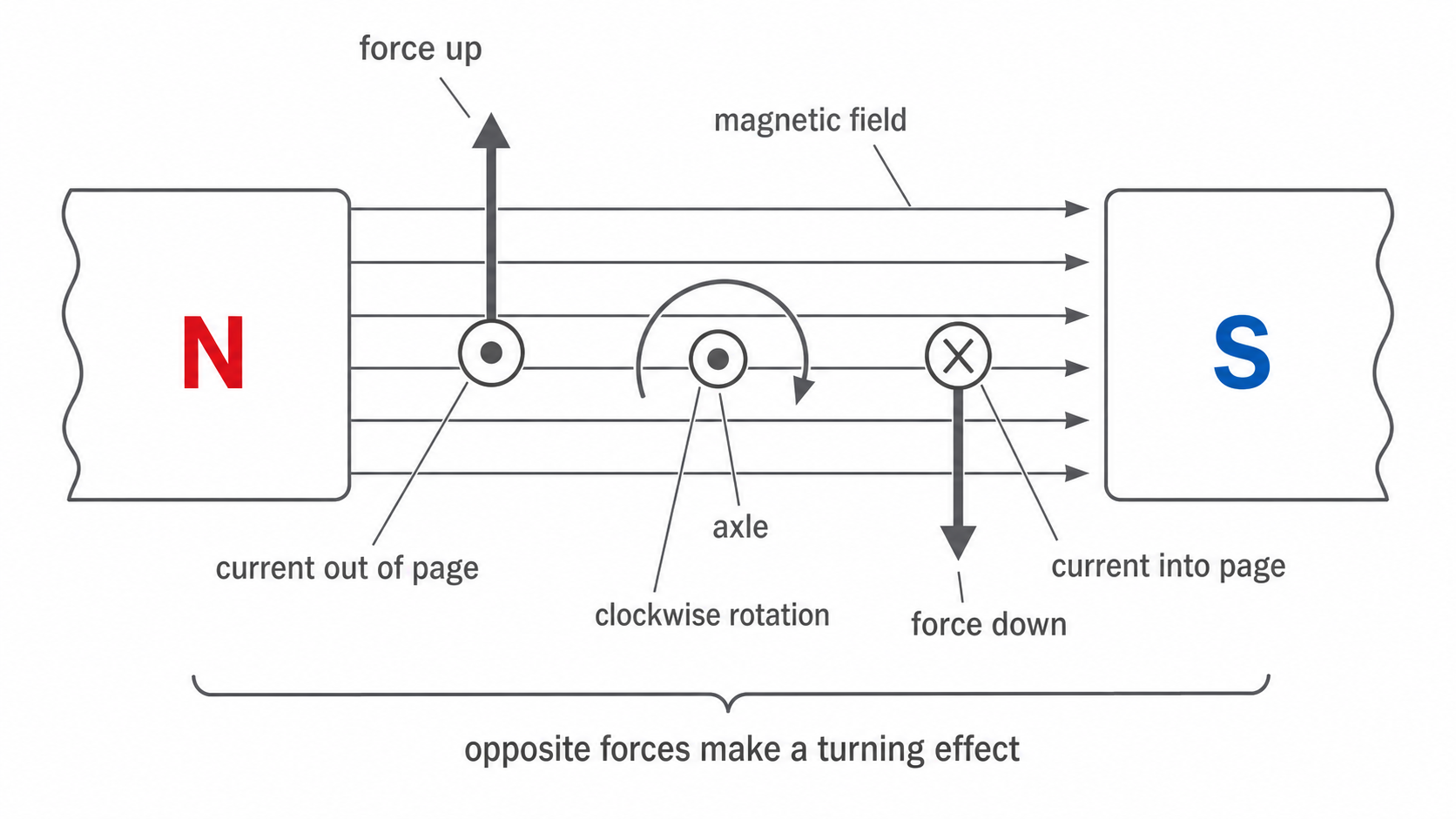
The two forces do not pull the whole coil in one straight direction. They act on different sides of the coil, so together they form a turning pair. That turning pair is why a current-carrying coil in a magnetic field tends to rotate.
Parts of a simple dc motor
A simple dc motor is the GCSE model for turning the motor effect into rotation. The parts that matter most for the explanation are the current-carrying coil, the magnetic field and the axle that lets the coil turn.
| Part | Job in the rotation explanation |
|---|---|
| coil of wire | carries current; its two sides experience forces in the magnetic field |
| permanent magnets | provide the magnetic field across the coil |
| axle | lets the turning effect rotate the coil |
| dc supply | provides the current |
[DIAGRAM: asset_name: Simple dc motor layout - diagram 2; asset_slug: 106_4_7_2_3_electric_motors_diagram2; file: diagram_assets/106_4_7_2_3_electric_motors_diagram2.png; recommended_method: image_gen; description: Exact labelled GCSE schematic of a simple dc motor on a white background. Show a rectangular coil on an axle between N and S pole pieces, a split-ring commutator on the axle, two fixed brushes touching the commutator, and a dc supply connected to the brushes. Label coil, axle, split-ring commutator, brushes, dc supply, magnetic field N to S. Deterministic drawing is required because component labels and connections are assessed.]
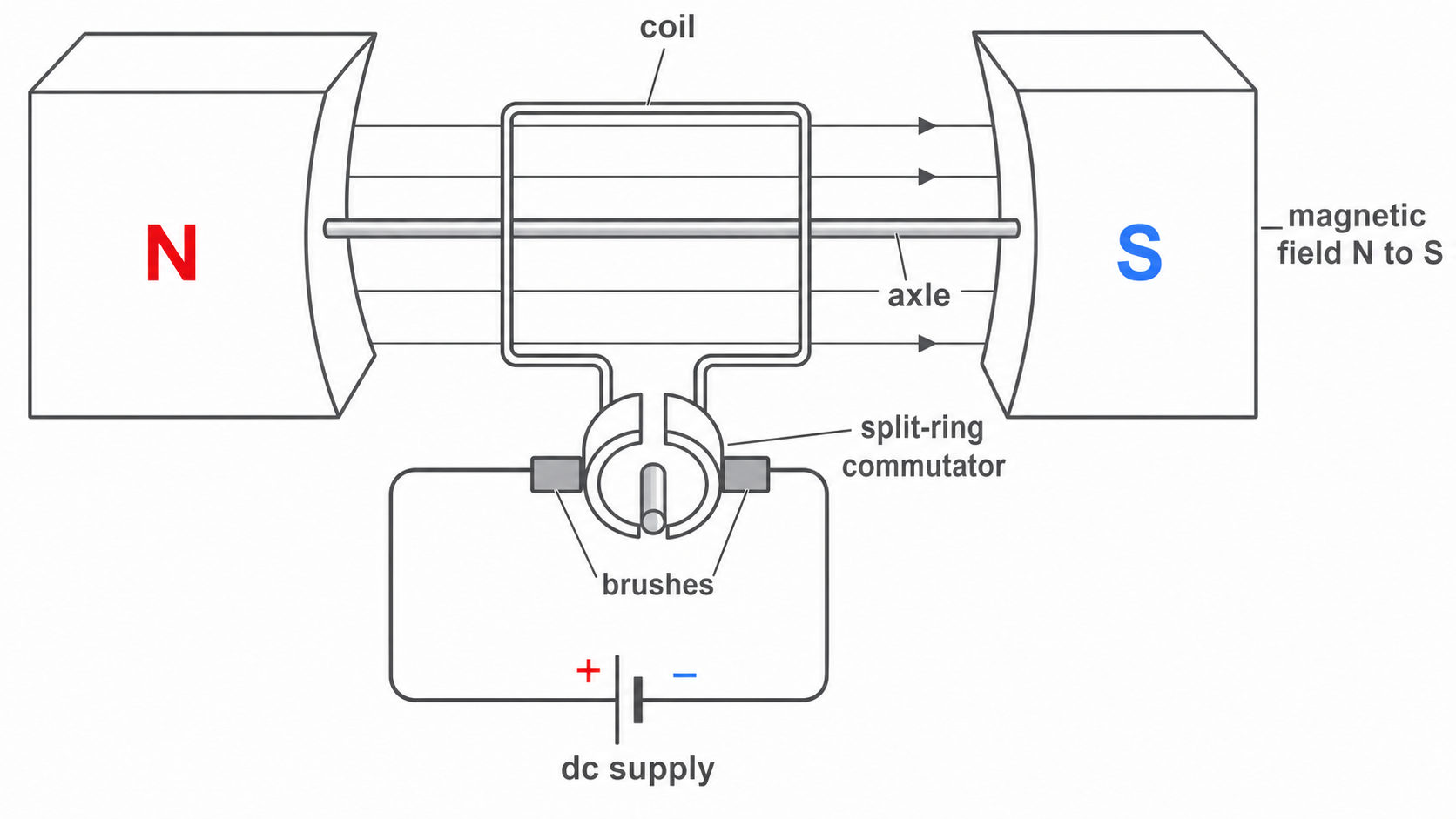
Many simple dc motor diagrams also show brushes and a split-ring commutator. Treat these as supporting context: the brushes pass current to the rotating coil, and the split-ring commutator reverses the current every half-turn so the rotation can continue in the same direction.
Continue this lesson.
You’re previewing NovaLearn without an account. Create a free account to read the rest.
Create free account