4.5.1.4b - Free-Body Diagrams and Resolving Forces
This Higher Tier lesson is about representing forces clearly when they do not all act in one straight line. You will use free-body diagrams to show the forces acting on one isolated object or system, and scale vector diagrams to resolve forces, show equilibrium, and determine resultants. The key habit is to treat forces as vectors: every force has a magnitude and a direction.
Isolating the object or system
A force diagram becomes much clearer when you first decide exactly what object or system you are analysing. This is called isolating the object or system. For example, you might choose the crate, the cyclist and bicycle together, or the hanging sign. Once you have chosen it, only show forces acting on that chosen object or system.
Free-body diagram
A free-body diagram is a simplified diagram showing the forces acting on one isolated object or system.
The word isolated does not mean that no forces act. It means you have separated the chosen object from its surroundings in your thinking. The surroundings can still exert forces on the object, such as weight, normal contact force, friction, air resistance, tension or thrust.
Do not include forces that the chosen object exerts on something else. If a book rests on a table, the table pushes up on the book and the Earth pulls down on the book. Those are forces acting on the book. The force the book exerts on the table belongs on a different diagram, because it acts on the table.
Reading free-body diagrams
On a free-body diagram, each arrow represents a force vector. The arrow direction shows the direction of the force. The arrow length can show relative magnitude: a longer arrow represents a larger force than a shorter arrow when the diagram is being used qualitatively.
[DIAGRAM: asset_name: free-body diagrams for balanced and unbalanced forces - diagram 1; asset_slug: 057_4_5_1_4b_free_body_diagrams_and_resolving_forces_diagram1; file: diagram_assets/057_4_5_1_4b_free_body_diagrams_and_resolving_forces_diagram1.png; recommended_method: image_gen; description: Assessed visual comparing two free-body diagrams. Left: block on a horizontal surface with equal upward normal contact force and downward weight, labelled resultant force = 0 N. Right: cyclist system with normal contact force and weight balanced vertically, driving force 180 N to the right and air resistance 120 N to the left, labelled resultant 60 N to the right. Students should learn how arrow direction and relative arrow length show balanced and unbalanced forces.]
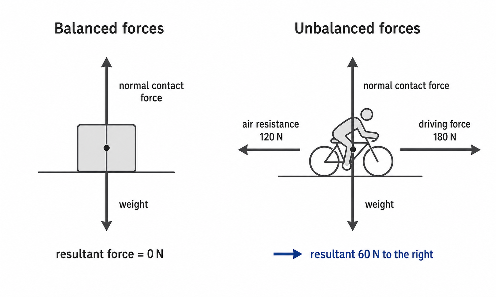
Balanced forces mean the resultant force is zero. For example, if the upward normal contact force on a resting block is equal in magnitude to the downward weight, those two vertical forces cancel. The free-body diagram shows this with equal-length arrows in opposite directions.
Unbalanced forces give a non-zero resultant. In the cyclist example, the upward and downward forces cancel, but the horizontal forces do not. A 180 N driving force to the right and a 120 N air resistance force to the left have a resultant of 60 N to the right.
Resultant force
The resultant force is the single force that has the same effect as all the forces acting together.
Balanced forces do not mean "no forces". They mean the forces cancel overall. An object with zero resultant force may be stationary, or it may already be moving at a constant velocity.
Resolving a force into components
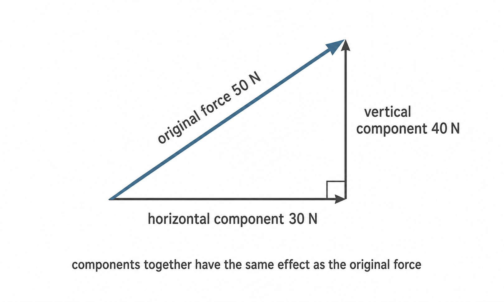
A single force at an angle can be resolved into two perpendicular components. The two component forces together have the same effect as the original single force.
The components are not extra forces that must be added to the original force. They are an alternative way to represent the original force. If you replace a diagonal force with its two components, do not also count the diagonal force when finding the resultant.
[DIAGRAM: asset_name: resolving a force into perpendicular components - diagram 2; asset_slug: 057_4_5_1_4b_free_body_diagrams_and_resolving_forces_diagram2; file: diagram_assets/057_4_5_1_4b_free_body_diagrams_and_resolving_forces_diagram2.png; recommended_method: image_gen; description: Assessed vector diagram showing a 50 N diagonal force resolved into perpendicular 30 N horizontal and 40 N vertical components using a 3-4-5 scale triangle. Include a right-angle marker, arrows labelled horizontal component 30 N and vertical component 40 N, and a note that components together have the same effect as the original force. Vector direction, perpendicularity, labels and relative scale are assessed.]
Continue this lesson.
You’re previewing NovaLearn without an account. Create a free account to read the rest.
Create free account