4.6.1.3a - Reflection of Waves
When a wave reaches a boundary between two different materials, the wave does not simply "stop". Some wave energy may be reflected, some may be transmitted into the next material, and some may be absorbed by the material at the boundary. This Physics-only lesson focuses on those boundary effects and on how to construct a ray diagram for reflection.
Material Interfaces
A material interface is a boundary where one material meets another. Examples include air meeting glass, water meeting a wall in a ripple tank, or air meeting a hard surface when sound reaches a wall.
Material Interface
A material interface is the boundary between two different materials.
When a wave reaches an interface, three effects are possible:
| Effect | What happens to the wave energy |
|---|---|
| reflection | some energy stays in the original material as a reflected wave |
| transmission | some energy passes into or through the second material |
| absorption | some energy is transferred to the material at the boundary |
These effects can happen together. For example, a sound wave reaching a wall may partly reflect back into the room, partly pass through the wall, and partly be absorbed by the wall. The exact amounts depend on the wave and on the materials, but the GCSE idea is the same: the interface changes what happens to the wave energy.
Ray Diagrams for Reflection
A ray diagram represents the direction a wave travels using straight lines with arrows. For reflection at a flat surface, the ray approaching the surface is the incident ray. The ray leaving the surface is the reflected ray.
The normal is an imaginary construction line drawn at 90 degrees to the surface at the point where the ray hits. Angles in reflection diagrams are measured between the ray and the normal, not between the ray and the surface.
Normal
The normal is a line drawn at right angles to a surface at the point where a ray meets the surface.
[DIAGRAM: asset_name: Reflection of Waves - diagram 1; asset_slug: 086_4_6_1_3a_reflection_of_waves_diagram1; file: diagram_assets/086_4_6_1_3a_reflection_of_waves_diagram1.png; recommended_method: image_gen; description: Image-generated educational ray diagram for reflection at a flat surface. It shows a horizontal reflecting surface, a dashed normal at 90 degrees to the surface, an incident ray approaching the surface, a reflected ray leaving the surface, arrows for wave direction, and angle labels i = 40 degrees and r = 40 degrees measured from the normal.]
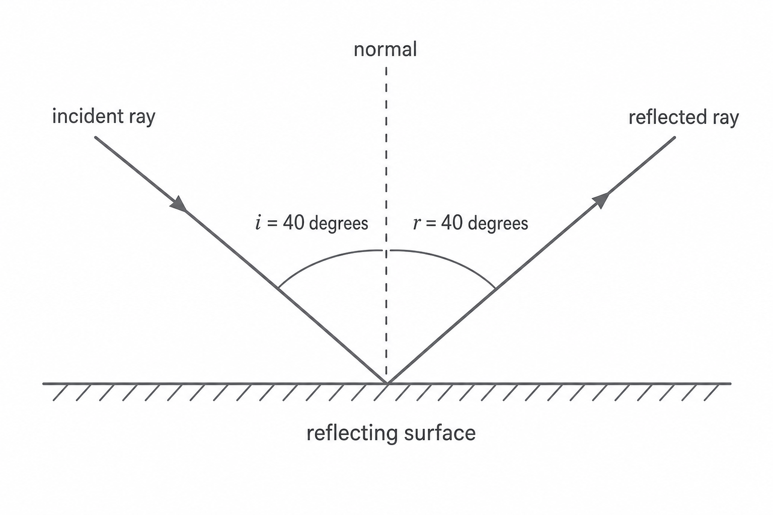
To construct a reflection ray diagram:
- Draw the reflecting surface.
- Mark the point where the incident ray meets the surface.
- Draw the normal at 90 degrees to the surface at that point.
- Measure the angle of incidence between the incident ray and the normal.
- Draw the reflected ray on the other side of the normal at the same angle.
- Add arrows to show the direction of travel.
Law of Reflection
The angle of incidence is often labelled i. The angle of reflection is often labelled r. In a correct reflection ray diagram, i = r.
Using the Law of Reflection
The law of reflection is simple, but exam questions often check whether you measured the angle from the correct line. If a ray hits a surface at 35 degrees to the normal, the reflected ray also leaves at 35 degrees to the normal.
If the angle is given to the surface instead, convert it first. The surface and the normal are at 90 degrees, so a ray at 60 degrees to the surface is at 30 degrees to the normal. The angle of reflection would then be 30 degrees.
The ray diagram is a model. It does not show every crest and trough in the wave; it shows the path of the wave energy in a clear geometric way.
Continue this lesson.
You’re previewing NovaLearn without an account. Create a free account to read the rest.
Create free account