4.7.3.2 - Uses of the generator effect
This Physics-only Higher-tier lesson is about how the generator effect is used in two devices: an alternator and a dynamo. Both involve motion in a magnetic field, but their output connections make their potential-difference graphs look different. By the end, you should be able to explain how each device works and identify its p.d.-time graph.
From generator effect to generators
The generator effect happens when a conductor moves relative to a magnetic field, or when the magnetic field around a conductor changes. A potential difference is induced across the conductor. If the conductor is part of a complete circuit, an induced current flows.
Generator effect
The generator effect is the induction of a potential difference across a conductor when it moves relative to a magnetic field, or when the magnetic field around it changes.
A generator uses this effect to transfer energy mechanically into an electrical output. In the simple GCSE model, a coil of wire is rotated between magnetic poles. As the coil turns, different sides of the coil cut through the magnetic field lines, so the induced potential difference changes during the rotation.
[DIAGRAM: asset_name: Rotating coil generator effect - diagram 1; asset_slug: 109_4_7_3_2_uses_of_the_generator_effect_diagram1; file: diagram_assets/109_4_7_3_2_uses_of_the_generator_effect_diagram1.png; recommended_method: image_gen; description: Schematic of a rectangular coil rotating between north and south pole magnets, with field direction, rotation arrow, two coil positions labelled zero generated p.d. and maximum generated p.d., and a note that mechanical rotation produces a changing induced p.d. through the generator effect. Nearby prose supplies the assessed detail.]
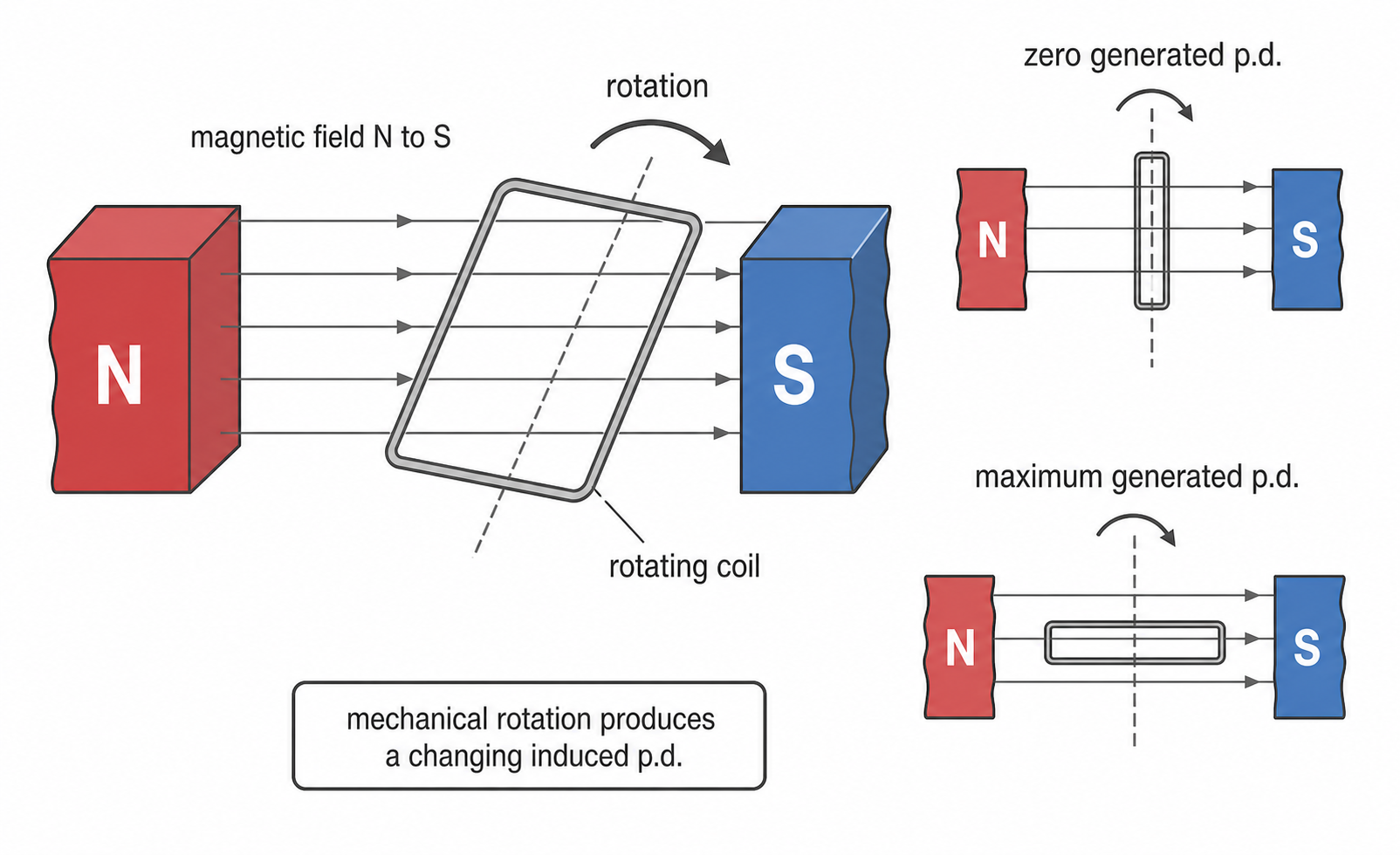
The graph of generated potential difference against time depends on how the coil is connected to the external circuit. That is the key difference between an alternator and a dynamo.
Alternators generate ac
An alternator is a generator that produces alternating potential difference and alternating current. In a simple alternator, a coil rotates in a magnetic field. The two ends of the coil are connected to two separate slip rings, and stationary brushes touch the slip rings to connect the coil to the external circuit.
Alternator
An alternator is a generator that uses the generator effect to generate ac.
Slip rings are complete rings. Each end of the coil stays connected to the same brush as the coil rotates. During the rotation, the direction of the induced potential difference in the coil reverses every half-turn, so the output across the external circuit also reverses direction. That is why the alternator output is ac.
[DIAGRAM: asset_name: Alternator with ac output graph - diagram 2; asset_slug: 109_4_7_3_2_uses_of_the_generator_effect_diagram2; file: diagram_assets/109_4_7_3_2_uses_of_the_generator_effect_diagram2.png; recommended_method: image_gen; description: Image-generated labelled alternator schematic showing a rotating rectangular coil between N and S magnets, two separate slip rings, two brushes, an external load, and a p.d.-time graph for one complete revolution. The graph crosses zero and has positive and negative halves labelled ac output. Generated with built-in Codex Image Gen; labels, graph shape and connection geometry remain the assessed content.]
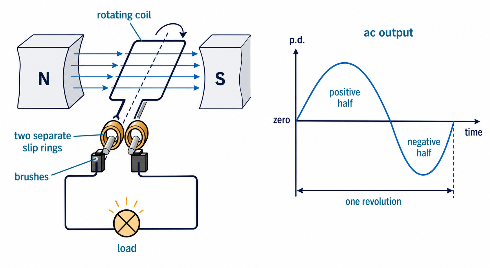
On a p.d.-time graph, an alternator output is shown as a smooth repeating curve that crosses the zero line. The positive and negative parts mean the polarity of the output has reversed. The exact starting point can change the graph from a sine-like curve to a cosine-like curve, but an ac trace must alternate above and below zero.
Dynamos generate dc
A dynamo is a generator that produces direct current. The rotating coil and magnetic field are similar to the alternator, but the connection to the external circuit is different.
Dynamo
A dynamo is a generator that uses the generator effect to generate dc.
A simple dynamo uses a split-ring commutator instead of two separate slip rings. The split ring has two insulated halves. As the coil completes each half-turn, the split ring swaps which brush each end of the coil is connected to.
This swap matters because it happens at the same time as the induced potential difference in the rotating coil would reverse. The external connections are reversed too, so the output to the external circuit remains in the same direction. The output is dc, but it is usually pulsed dc: the potential difference changes size and returns to zero between peaks.
Continue this lesson.
You’re previewing NovaLearn without an account. Create a free account to read the rest.
Create free account