4.5.4 - Calculating Moments and Transmitting Rotation
A force can make an object rotate if it acts away from a pivot. This turning effect is called a moment. In this physics-only lesson you will calculate moments, use balanced clockwise and anticlockwise moments, and explain how simple levers and gears transmit rotational effects.
Forces that cause rotation
A pivot is the fixed point or turning point about which an object can rotate. A door rotates about its hinges, a spanner rotates about the centre of a nut, and a seesaw rotates about its central support.
The turning effect of a force is called the moment of the force.
Moment of a Force
The moment of a force is the turning effect of the force about a pivot.
The size of the moment depends on two quantities:
- the size of the force
- the perpendicular distance from the pivot to the line of action of the force
The line of action is the straight line in the direction in which the force acts. The distance in the moments equation is measured at right angles from the pivot to that line. This is why a force applied through the pivot has no moment: the perpendicular distance is 0 m.
[DIAGRAM: asset_name: moment_perpendicular_distance - diagram 1; asset_slug: 062_4_5_4_moments_levers_and_gears_diagram1; file: diagram_assets/062_4_5_4_moments_levers_and_gears_diagram1.png; recommended_method: image_gen; description: Assessed force-and-moment diagram generated with built-in Codex Image Gen showing a horizontal bar with a left-hand pivot, a downward force on the right, the force's dashed line of action, the perpendicular distance d from the pivot to that line of action, a right-angle marker, a clockwise moment arrow, and the equation M = Fd with units. Force direction, pivot position, distance definition and labels carry assessed meaning.]
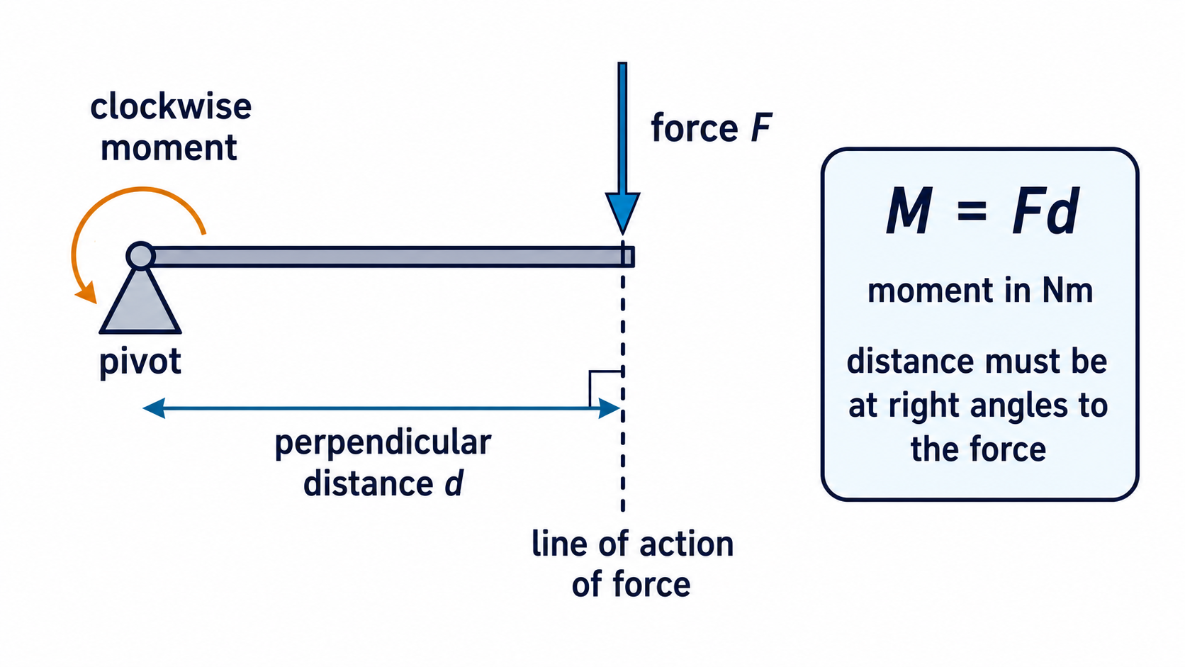
The moment can be clockwise or anticlockwise. For example, a downward force on the right-hand side of a pivot usually gives a clockwise moment. A downward force on the left-hand side usually gives an anticlockwise moment.
Moment of a force
In this equation:
| Symbol | Quantity | Unit |
|---|---|---|
M | moment of a force | newton-metres, Nm |
F | force | newtons, N |
d | perpendicular distance from the pivot to the line of action of the force | metres, m |
AQA's specification labels this equation as one students should be able to recall and apply. For the 2026 and 2027 exam arrangements, AQA also provides the Physics equation sheet, so the key skill is recognising when to use M = Fd, choosing the perpendicular distance, converting to metres, and rearranging the equation correctly.
Calculating moments
A moments calculation should show the relationship, substitution, answer and unit. The most common mistake is using centimetres without converting them to metres.
Worked example 1: A 12 N force acts 0.25 m from a pivot. The force is perpendicular to the bar. Calculate the moment.
Use:
Substitute:
Answer:
M = 3.0 Nm
If the force would turn the object clockwise, you may describe this as a clockwise moment of 3.0 Nm.
Worked example 2: A student pushes down on a handle with a force of 40 N. The perpendicular distance from the pivot to the force's line of action is 35 cm. Calculate the moment.
First convert the distance:
35 cm = 0.35 m
Then calculate:
Answer:
M = 14 Nm
Do not use the length of a sloping handle unless that length is already the perpendicular distance. In many exam diagrams, the safest route is to identify the pivot, draw or imagine the force's line of action, and then use the shortest right-angle distance from the pivot to that line.
Balanced moments
An object can be balanced even when forces act on both sides of a pivot. The condition for rotational balance is about moments, not just force sizes.
If an object is balanced:
total clockwise moment = total anticlockwise moment
This comparison must be made about the same pivot. If there is more than one clockwise moment, add them to find the total clockwise moment. If there is more than one anticlockwise moment, add them to find the total anticlockwise moment.
[DIAGRAM: asset_name: balanced_clockwise_anticlockwise_moments - diagram 2; asset_slug: 062_4_5_4_moments_levers_and_gears_diagram2; file: diagram_assets/062_4_5_4_moments_levers_and_gears_diagram2.png; recommended_method: image_gen; description: Exact assessed balanced-beam diagram with a central pivot, a 30 N downward force 0.40 m to the left producing an anticlockwise moment, and a 20 N downward force 0.60 m to the right producing a clockwise moment. Calculation boxes show 30 x 0.40 = 12 Nm and 20 x 0.60 = 12 Nm, so the beam is balanced. Deterministic drawing is required because the distances, forces, directions and equality of moments are assessed details.]
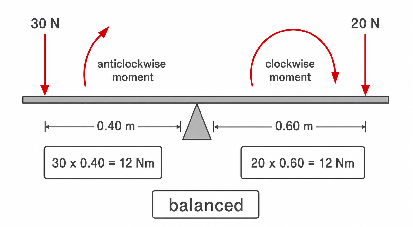
In the diagram, the forces are not equal, but the moments are equal:
Continue this lesson.
You’re previewing NovaLearn without an account. Create a free account to read the rest.
Create free account