4.6.1.3b - Required Practical 9 - Reflection and Refraction
This physics-only required practical investigates what happens when light meets a boundary between materials. You use a ray box to trace reflected and refracted rays, then measure angles with a protractor. The important practical skill is not just seeing the rays; it is setting up the normal correctly, recording angles in degrees, and using the data to compare surfaces and transparent substances.
Aim and ray language
The practical has two linked aims:
- investigate the reflection of light by different types of surface
- investigate the refraction of light by different transparent substances
When light reaches a boundary, more than one thing can happen. Some light may be reflected back from the boundary. Some light may be transmitted into the next material. If the transmitted light changes direction as it enters the new material, it has been refracted.
Normal
The normal is an imaginary line drawn at 90 degrees to a surface at the point where the ray hits the surface.
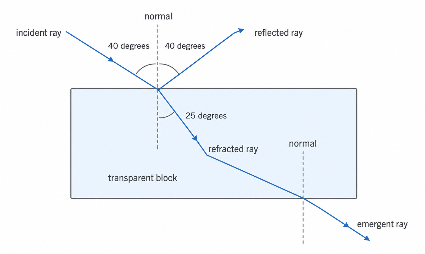
Angles in this practical are always measured from the normal, not from the surface. The angle of incidence is between the incident ray and the normal. The angle of reflection is between the reflected ray and the normal. The angle of refraction is between the refracted ray inside the new material and the normal.
For reflection from a smooth surface, the law of reflection predicts:
Law of reflection
For refraction, the angle of refraction depends on the material. If the angle of incidence is kept the same, different transparent substances can give different angles of refraction.
Apparatus and setup
The usual apparatus includes:
- a ray box and suitable power supply
- a single slit to make a narrow ray
- two rectangular transparent blocks made from different substances, such as glass and Perspex or acrylic
- a 30 cm ruler
- a protractor
- plain A3 paper
- a pencil for marking crosses and ray paths
- surface samples for reflection, such as smooth/shiny and rough/matt surfaces, if your school uses a separate surface comparison
[DIAGRAM: asset_name: Required Practical 9 Reflection and Refraction - diagram 1; asset_slug: 087_4_6_1_3b_required_practical_9_reflection_and_refraction_diagram1; file: diagram_assets/087_4_6_1_3b_required_practical_9_reflection_and_refraction_diagram1.png; recommended_method: image_gen; description: Image-generated apparatus layout for required practical 9. Shows A3 paper, a rectangular transparent block traced on the paper, a surface line, normal labelled N at 90 degrees, ray box with slit producing a narrow incident ray, reflected ray, refracted ray inside the block and emergent ray, plus ruler and protractor.]
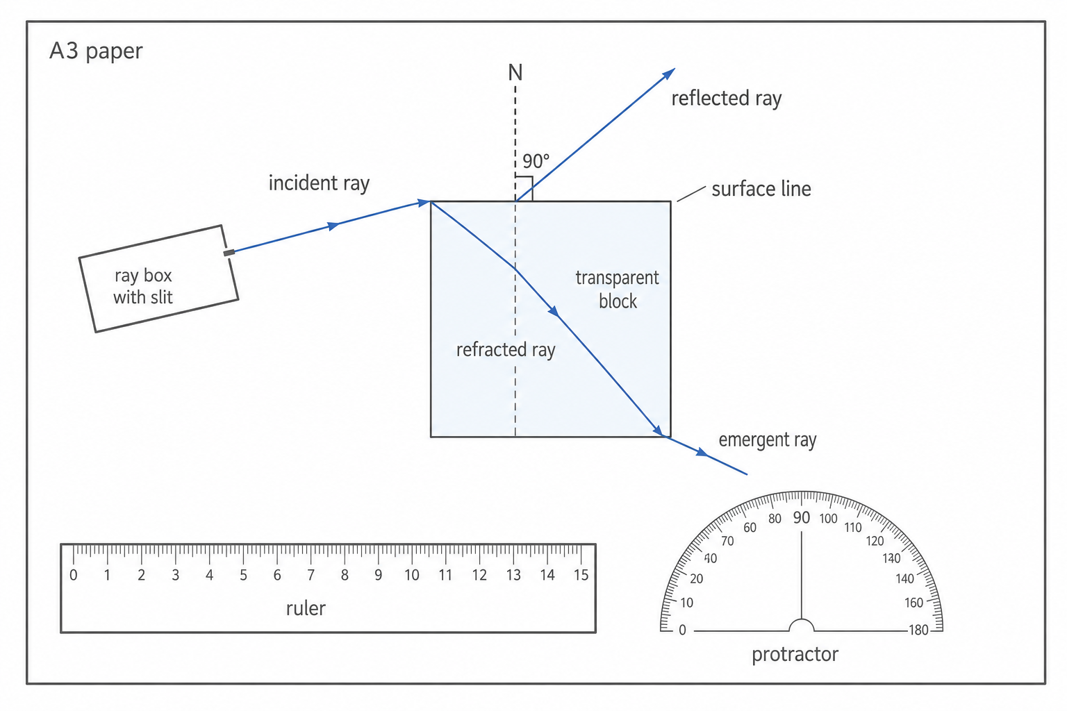
Set up the paper before switching on the ray box:
- Place a ruler near the middle of the A3 paper and draw a straight line for the surface of the block or reflecting surface.
- Use a protractor to draw a second line at 90 degrees to the surface line.
- Label this second line
Nfor normal. - Place the transparent block so one face lies on the surface line and the normal passes through the middle of that face.
- Draw carefully around the block so it can be returned to exactly the same position.
The ray box produces a narrow beam of light. Use a slit so the ray is thin enough to mark accurately. Low light conditions can make the ray easier to see, but the room must still be safe to move around in.
The ray box can get hot. Switch it off when you are not taking readings, handle it carefully, and avoid looking directly into the bright ray.
Reflection method
To investigate reflection, keep the point where the ray hits the surface fixed. Change either the angle of incidence or the surface being tested, but do not change both at the same time if you want a fair comparison.
[DIAGRAM: asset_name: Required Practical 9 Reflection and Refraction - diagram 2; asset_slug: 087_4_6_1_3b_required_practical_9_reflection_and_refraction_diagram2; file: diagram_assets/087_4_6_1_3b_required_practical_9_reflection_and_refraction_diagram2.png; recommended_method: image_gen; description: Image-generated comparison of reflection from a smooth/shiny surface and a rough/matt surface. The smooth surface has one clear reflected ray with angle of incidence equal to angle of reflection measured from the normal. The rough surface has the same incoming ray but scattered reflected rays in different directions because the local surface directions vary.]
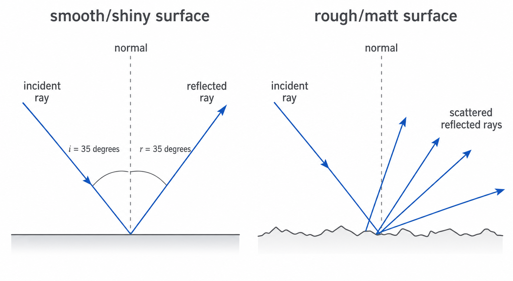
A method for reflection:
- Put the chosen reflecting surface on the surface line.
- Direct a narrow incident ray at the point where the normal meets the surface.
- Mark two small crosses along the incident ray and two small crosses along the reflected ray.
- Switch off the ray box and remove the surface if needed.
- Join each pair of crosses with a ruler to draw the incident and reflected rays.
- Measure the angle of incidence and angle of reflection from the normal.
- Repeat for a range of angles of incidence, such as 20 degrees, 30 degrees, 40 degrees and 50 degrees.
- Repeat for another surface, keeping the method and angles of incidence the same.
For a smooth shiny surface, the reflected ray is usually clear and narrow. For a rough or matt surface, the reflected light is scattered, so there may not be one clear reflected ray to mark. That observation is still useful evidence about the type of reflection, but if the ray is too spread out the angle measurement will be less reliable.
When comparing surfaces, a fair test needs control variables. Use the same ray box, slit, distance from the surface, angle of incidence, room lighting and method for marking rays. If only the surface type changes, differences in the reflected ray are more likely to be due to the surface.
Refraction method
Refraction is investigated using transparent blocks made from different substances. The independent variable can be the substance, such as glass compared with Perspex. The dependent variable is the angle of refraction. The angle of incidence should be controlled when comparing the substances.
[DIAGRAM: asset_name: Required Practical 9 Reflection and Refraction - diagram 3; asset_slug: 087_4_6_1_3b_required_practical_9_reflection_and_refraction_diagram3; file: diagram_assets/087_4_6_1_3b_required_practical_9_reflection_and_refraction_diagram3.png; recommended_method: image_gen; description: Image-generated refraction ray diagram through a rectangular block. Shows the normal, incident ray at 40 degrees to the normal, reflected ray at 40 degrees, refracted ray inside the block at 25 degrees toward the normal, emergent ray from the far face, and all angles measured from the normal.]
Continue this lesson.
You’re previewing NovaLearn without an account. Create a free account to read the rest.
Create free account