6.3.3(a)-(e) - Flux, Faraday's and Lenz's laws and generators
Electromagnetic induction is how changing magnetic fields become measurable e.m.f.s. In this lesson you will define magnetic flux and flux linkage, use Faraday's law and Lenz's law, describe how search coils investigate changing flux, and explain the simple a.c. generator. The important OCR habit is to say exactly what changes: magnetic flux linkage, not just "magnetism".
Magnetic flux and the weber
Magnetic flux is a way of measuring how much magnetic field passes through an area. Imagine a loop of wire in a uniform magnetic field. If the field passes straight through the face of the loop, the flux is large. If the loop is turned edge-on to the field, almost no field passes through the area, so the flux is zero.
Magnetic flux
Magnetic flux, , through a flat area in a uniform magnetic field is the product of magnetic flux density, area, and the cosine of the angle between the magnetic field and the normal to the area.
Magnetic flux
Here is magnetic flux density in tesla (T), is the area in square metres (), and is the angle between the magnetic field direction and a line normal to the area. The unit of magnetic flux is the weber, .
Because is in and is in ,
[DIAGRAM: asset_name: 6.3.3(a)-(e) - Flux, Faraday's and Lenz's laws and generators - diagram 1; asset_slug: 6_03_3a_magnetic_flux_faraday_lenz_and_generators__diagram_01; recommended_method: drawn_physics; caption: Magnetic flux depends on the angle between the field and the normal to the coil plane.; description: Edge-on area geometry shows the normal perpendicular to the plane and angle to the field; cosine graph.]
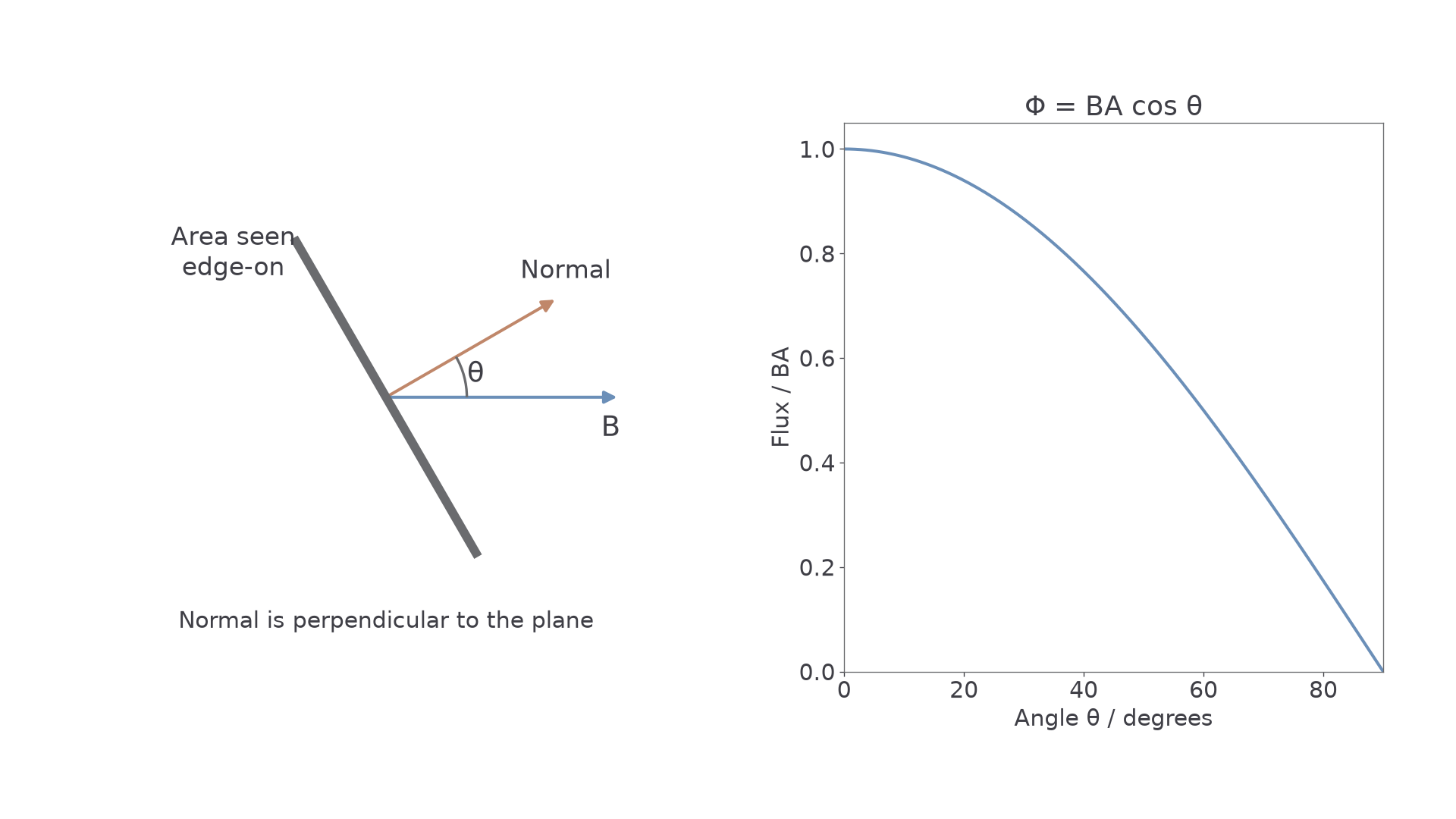
The angle is the common trap. In , is not the angle between the magnetic field and the plane of the coil. It is the angle between the magnetic field and the normal to the plane. The normal is a line at right angles to the coil face.
If , the field is parallel to the normal, so the field passes straight through the coil face:
If , the field is parallel to the plane of the coil, so no field passes through the area:
Worked example: flux through a coil
A rectangular coil has area . It is placed in a uniform magnetic field of flux density . The normal to the coil makes an angle of with the field. Calculate the magnetic flux through one turn.
Use:
Substitute:
The answer is less than , because the coil is tilted rather than face-on to the field.
Flux linkage and Faraday's law
A coil usually has more than one turn. If each turn links the same magnetic flux, the magnetic flux linkage is the number of turns multiplied by the flux through one turn.
Magnetic flux linkage
Magnetic flux linkage is , where is the number of turns of the coil and is the magnetic flux through each turn.
For a coil of identical turns in a uniform field:
The unit is often written as turns. The word "turns" is not a new SI base unit; it reminds you that the flux through one turn has been multiplied by the number of turns.
Electromagnetic induction happens when the magnetic flux linkage changes. It can change because the magnetic flux density changes, the coil area linked by the field changes, the angle changes, or the number of turns linked changes. In a generator, the angle changes continuously. In a search-coil experiment, the magnetic field may alternate or the coil may be rotated.
Faraday's law
The magnitude of the induced e.m.f. is proportional to the rate of change of magnetic flux linkage.
OCR gives the induction equation in the form:
Faraday's law
Here is the induced e.m.f. in volts (V), is the change in magnetic flux linkage in turns, and is the time interval in seconds. The minus sign is not a calculation nuisance. It represents Lenz's law, which you will use for direction in the next part.
For calculation magnitudes, OCR often accepts:
This tells you the average induced e.m.f. over the time interval. If the flux linkage changes non-uniformly, the instantaneous e.m.f. changes too; the largest e.m.f. occurs when the rate of change of flux linkage is greatest.
Worked example: average induced e.m.f.
A coil has turns. The magnetic flux through each turn changes from to in . Calculate the magnitude of the average induced e.m.f.
First calculate the magnitude of the change in flux per turn:
Then calculate the magnitude of the change in flux linkage:
Now use Faraday's law:
The average induced e.m.f. is . A shorter time for the same flux-linkage change would give a larger e.m.f.
Lenz's law and induction direction
Faraday's law gives the size of the induced e.m.f. Lenz's law gives its direction.
Lenz's law
The induced e.m.f. is in a direction such that the effects it produces oppose the change causing it.
The phrase "oppose the change" is precise. It does not mean "oppose the magnetic field" in every situation. It means the induced current, if a complete circuit is available, produces a magnetic effect that tries to reduce the change in magnetic flux linkage.
Use this two-step method for direction questions.
- Identify the change in magnetic flux linkage.
- Choose the induced effect that opposes that change.
Example: a north pole moves towards a coil
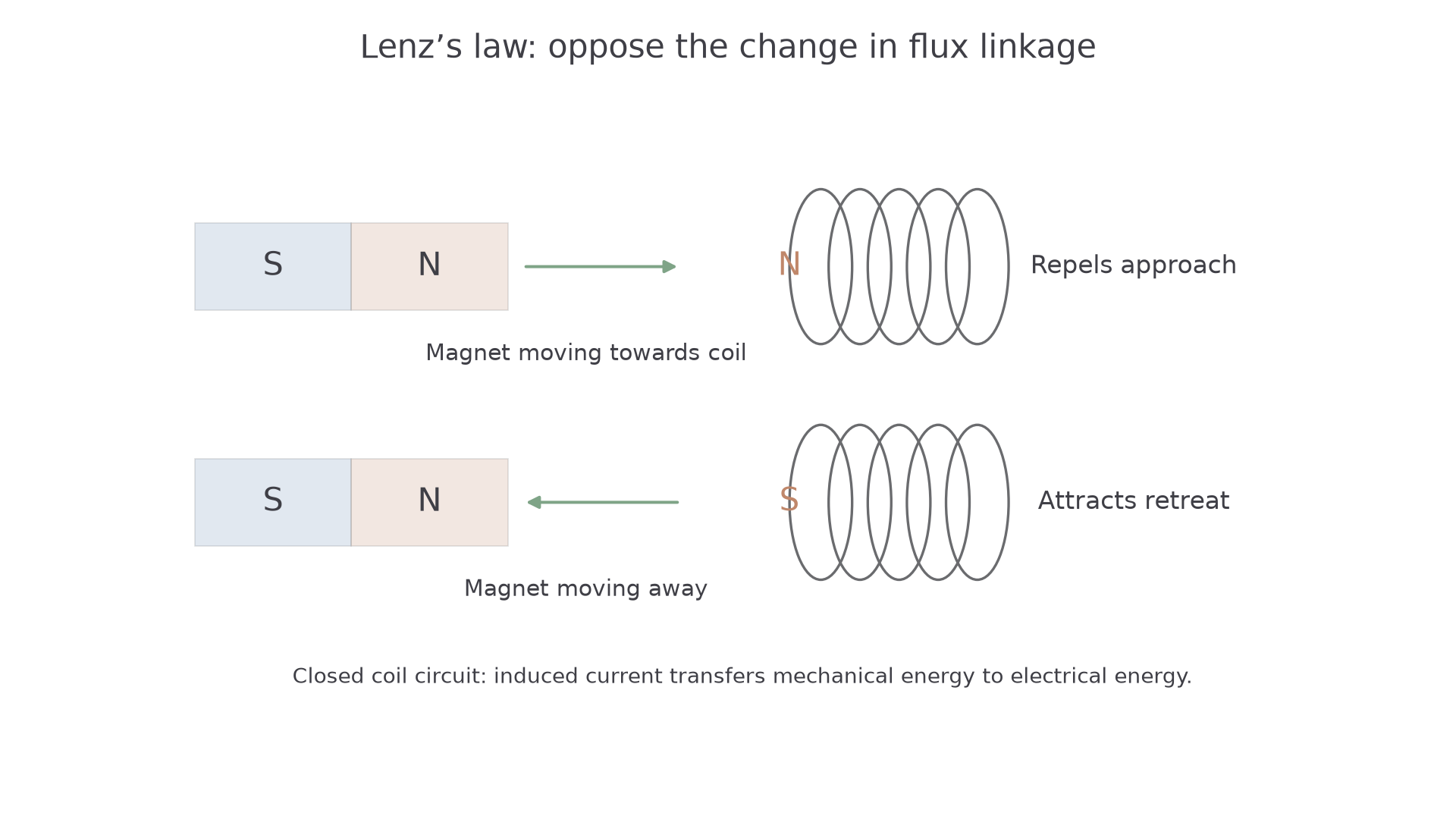
As the north pole approaches, the magnetic flux linkage through the coil increases. The induced current must produce a magnetic field that opposes this increase. The coil face nearest the magnet therefore behaves like a north pole, repelling the approaching north pole. The induced current direction is the one that gives that pole arrangement, found using the right-hand grip rule for a coil.
Example: a north pole is pulled away from a coil
Now the flux linkage through the coil is decreasing. The induced current must try to maintain it. The near face of the coil behaves like a south pole, attracting the receding north pole. The current direction is reversed compared with the approaching case.
This is an energy-conservation idea. If an induced current helped the original change, the change would grow without an energy input. In real induction, work must be done to move the magnet, turn the generator, or change the field. That input energy is transferred electrically and thermally in the circuit.
Graphs make Faraday and Lenz work together. If flux linkage is increasing, is positive, so the minus sign gives an e.m.f. in the negative chosen direction. If flux linkage is decreasing, the gradient is negative, so the induced e.m.f. has the opposite sign. If flux linkage is momentarily constant, the induced e.m.f. is zero even if the flux linkage itself is large.
[DIAGRAM: asset_name: 6.3.3(a)-(e) - Flux, Faraday's and Lenz's laws and generators - diagram 2; asset_slug: 6_03_3a_magnetic_flux_faraday_lenz_and_generators__diagram_02; recommended_method: drawn_physics; caption: An induced coil field opposes the approach or retreat of a north magnetic pole.; description: An approaching north pole induces a north coil face that repels it; a retreating north pole induces a south face that attracts it. The opposing effect requires external work.]
Continue this lesson.
You’re previewing NovaLearn without an account. Create a free account to read the rest.
Create free account