4.2.1 - Circuit symbols and diagrams
Circuit diagrams are the written language of electric circuits. In this lesson you will learn the common symbols used in OCR A Level Physics A, how to combine them into clear diagrams, and how to read what a diagram says about current paths and measuring instruments. The aim is not to calculate circuit values yet; it is to communicate and interpret circuits without ambiguity.
Symbols as a circuit language
A circuit symbol represents an electrical component or connection. A circuit diagram is not a realistic picture of the apparatus: it is a simplified map showing how components are connected.
Circuit diagram
A circuit diagram is a symbolic drawing of an electrical circuit. It shows the components and the electrical connections between them using standard symbols.
This matters because two circuits can look different on a bench but be electrically equivalent if the same components are joined between the same points. The diagram communicates the topology of the circuit: which points are joined, which components are in the same current path, and which components are connected across the same two points.
The OCR specification links this topic to HSW8, which is about communicating scientific information and ideas using appropriate terminology. In this lesson that means:
- use recognised symbols, not sketches of real objects
- draw wires as clear straight connections
- label meters and supplies clearly
- show junctions and crossings unambiguously
- keep the physical meaning of "series", "parallel" and "across" tied to connections, not to the visual position on the page
A circuit diagram tells you how components are connected, not where they physically sit on the bench.
Recognising common symbols
You do not need a formula sheet to tell you what a symbol means. You need to recognise the component and know any immediate diagram rule that goes with it.
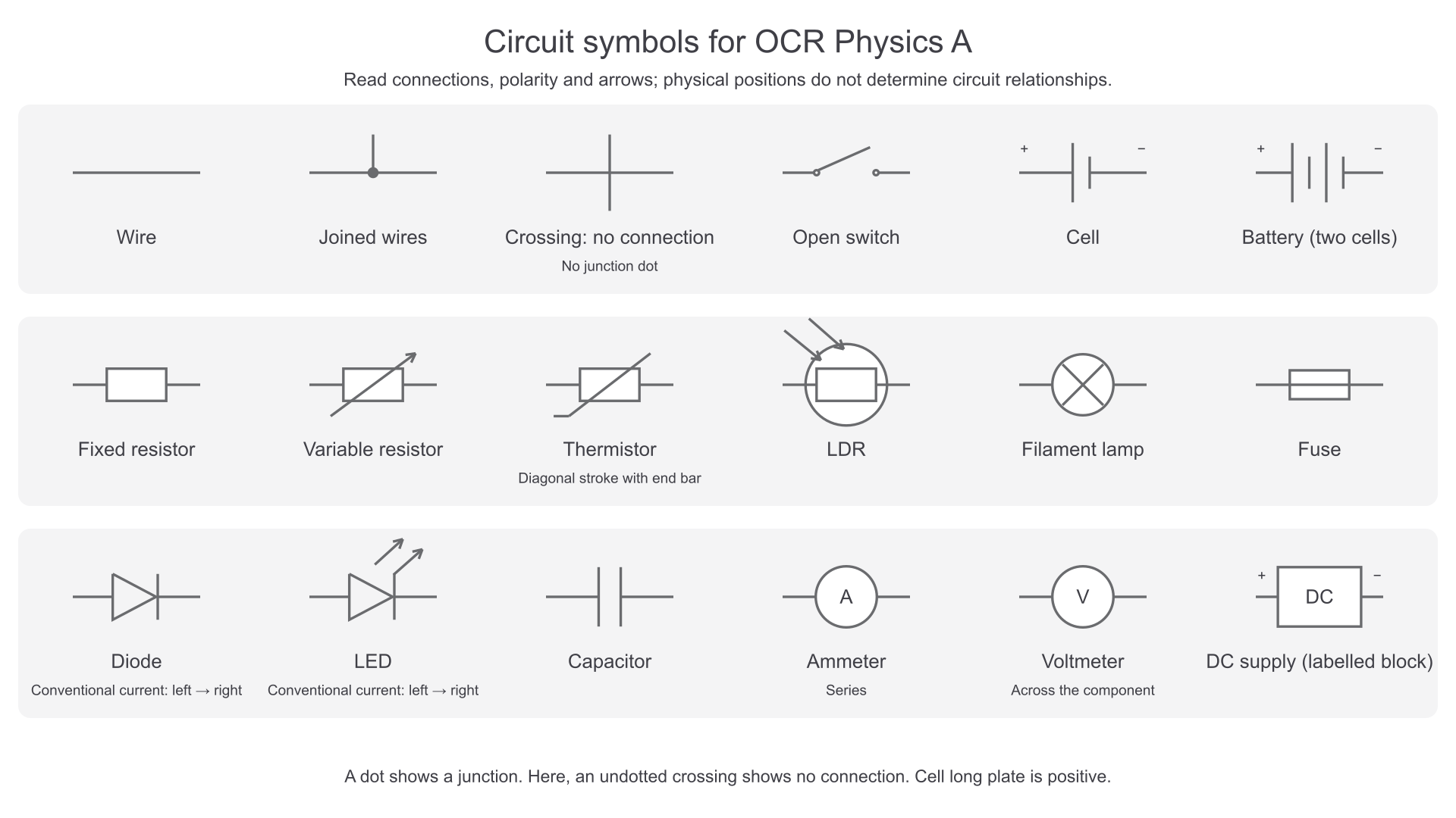
Sources provide the electrical supply. A cell is shown by one long line and one short line; the long line is the positive terminal. A battery is two or more cells. A DC power supply may be shown as a source symbol or as a labelled supply block in a practical diagram.
Control and resistance components affect the current path. A switch opens or closes the circuit. A fixed resistor is drawn as a rectangle. A variable resistor is a resistor with a diagonal arrow through it. A thermistor and an LDR are variable-resistance components controlled by temperature and light respectively, but their detailed behaviour is taught in later resistance and potential-divider lessons.
Meters must be placed according to what they measure.
Ammeter
An ammeter measures electric current. In a circuit diagram it is shown as a circle containing and is connected in series with the current path being measured.
Voltmeter
A voltmeter measures potential difference. In a circuit diagram it is shown as a circle containing and is connected in parallel across the component or section being measured.
Some component symbols also carry direction or polarity information. A diode or LED is connected with a preferred direction for conventional current. A capacitor symbol has two equal plates, so do not confuse it with a cell, which has one long and one short plate. A lamp is drawn as a circle with a cross inside; a fuse is a safety component in the current path.
Worked example: deciding what the symbol is saying
A diagram shows a long-short pair of parallel lines connected to a resistor rectangle and a circle containing .
- The long-short pair is a cell, not a capacitor.
- The long line is the positive terminal of the cell.
- The rectangle is a fixed resistor.
- The circle labelled is an ammeter, so it should lie in the same current path as the current being measured.
The diagram has already told you the type of source, one component, one measuring instrument and the direction of the source polarity before any calculation has started.
In the standard symbols, a thermistor has a diagonal stroke with a short bar at its end; a variable resistor has a diagonal arrow. The diode bar identifies the cathode: conventional forward current is towards that bar. LED arrows point away from the diode to represent emitted light, whereas an LDR’s arrows point towards the resistor. These differences communicate the component’s function, so retain them when redrawing a circuit.
[DIAGRAM: asset_slug: 4_02_1_circuit_symbols_and_diagrams__corrected_reference; description: Common circuit symbols and the conventions for joined and crossing wires.; caption: Standard circuit symbols, junctions and crossings.]
Drawing circuit diagrams
A clear circuit diagram should make the current paths easy to trace. Start by drawing the main loop, then add branches and meters. It is usually better to use straight horizontal and vertical wires than to draw a realistic layout of the apparatus.
Use this method when drawing a diagram from a written description:
- Identify the source and the main loop.
- Place any series components in the same loop.
- Add branches only where components are connected across the same two points.
- Add the ammeter in series with the component or branch current being measured.
- Add the voltmeter across the component or section whose p.d. is being measured.
- Check for polarity-sensitive components and for accidental short circuits.
The word "across" is important. A voltmeter across a thermistor has one lead connected to each side of the thermistor. It is not just "near" the thermistor on the page. It must share the same two connection points as the thermistor.
Worked example: drawing a measurement circuit
Continue this lesson.
You’re previewing NovaLearn without an account. Create a free account to read the rest.
Create free account